This project is still alive. I keep uploading new drawings and pictures (November 2022).
There is a bit of knowledge on internet how to build a homebrew duplexer. There are some better and worst websites instructing how to do it. Why am I create my own tutorial? Because I would like to show not only dimensions “A” and “B” but also I would like to explain why they are A and B, and also I would like to provide some mechanical solutions how to make every single part. You will have to be equipped with some tools like a lathe*, a spectrum analyser** and of course some other basic tools like drill, taps, screws, saws, metal files, screw drivers, sander etc etc etc etc…
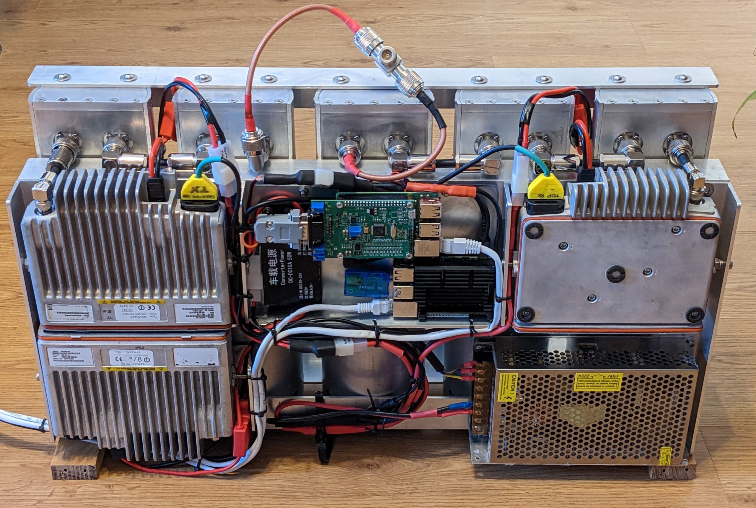
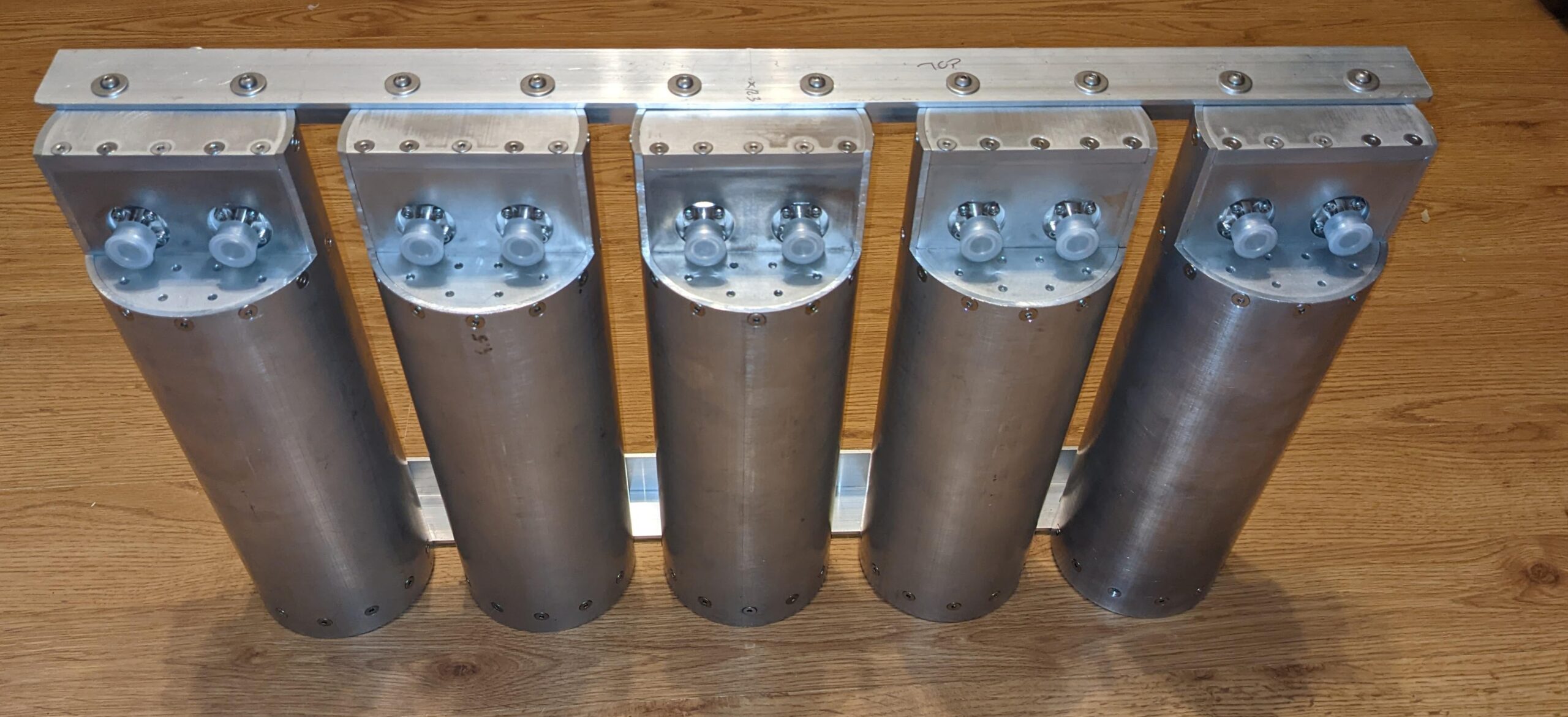
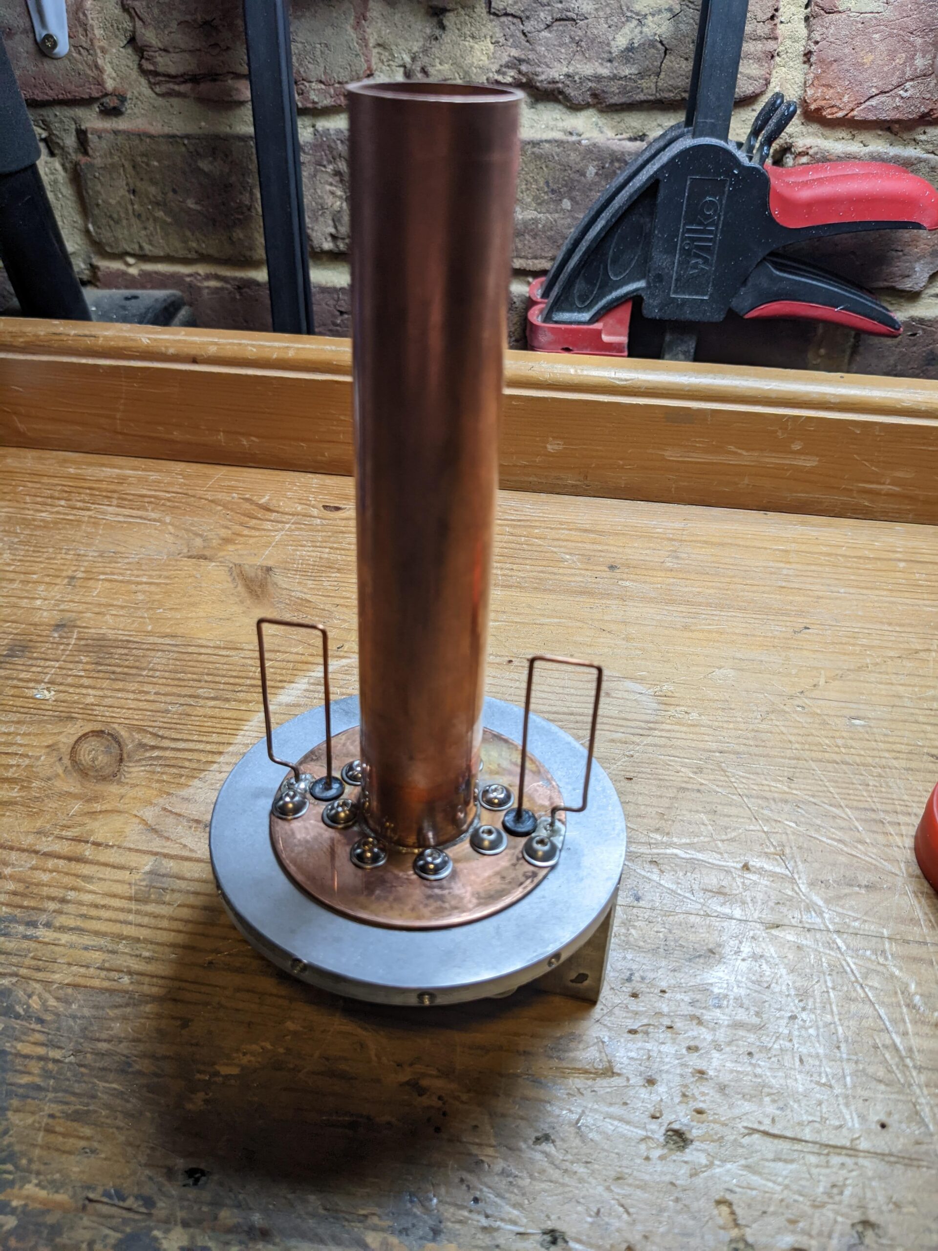
The homebrew duplexer presented below was created for a DMR UHF repeater with 9MHz offset, however, especially the offset does not matter, every cavity will have to be tuned to a desired frequency. The project is based on Bp-Br cavities. This particular project is called AL100 (as it is an aluminium cavity diameter 4 inches – 100 mm)
If you decide to follow my project, it will give you cavities with the 55dB notch attenuation (per cavity!) for 9MHz split @ 70cm UHF band and only 0.3dB loose at the resonance frequency (per cavity!). As a test i made a fully copper duplexer cavity version and notch attenuation was 65dB (9MHz split) which was 10dB greater (!) comparing to the standard aluminium version. However soldering everything was a disaster, so fully copper version was the only one off test!!!
Charts and spec to be seen here
Assembly drawing for RX Cavity:
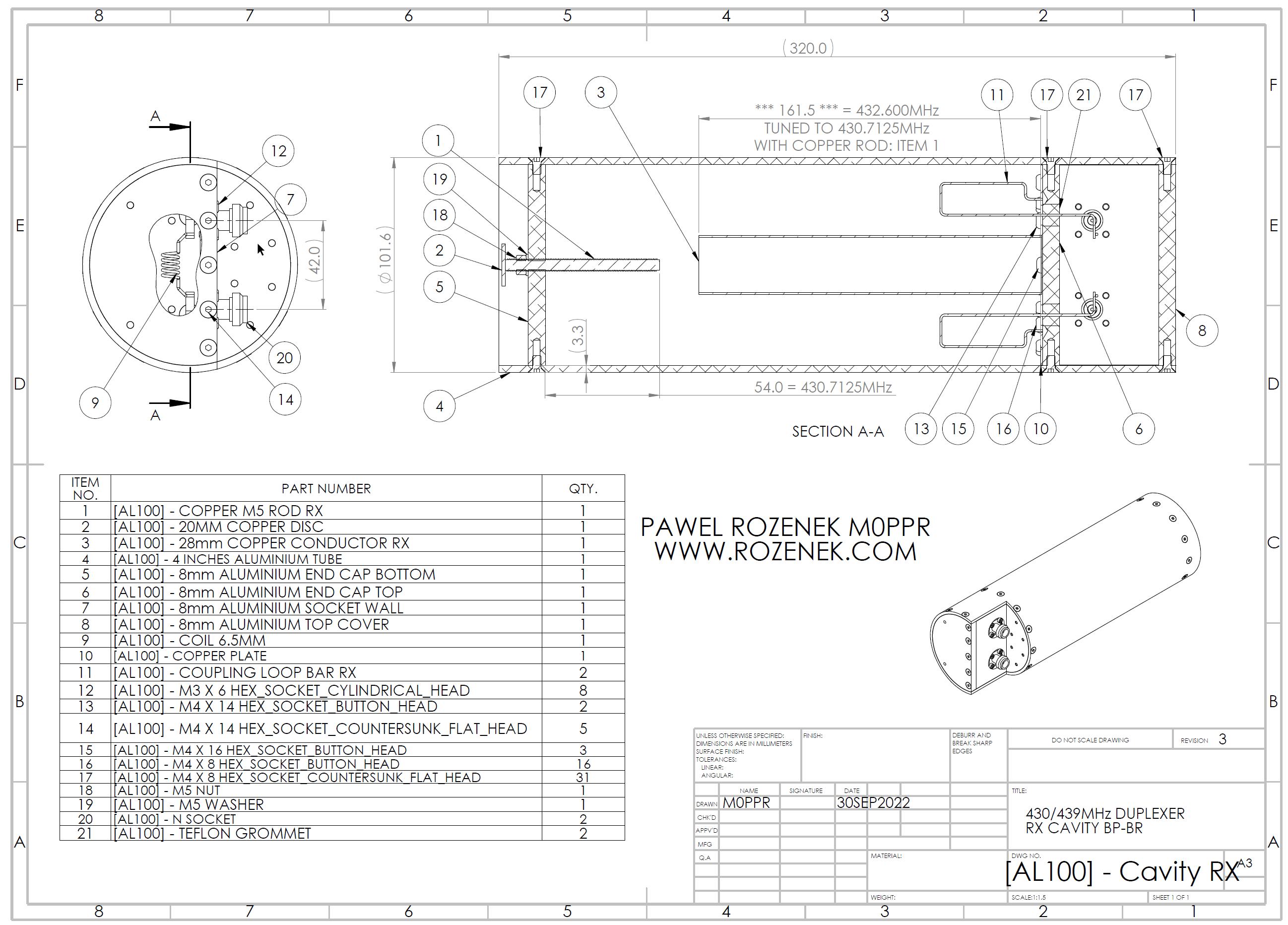
Item 1 – [AL100] – Copper M5 Rod RX
Item 2 – [AL100] – 20MM Copper Disk
Item 3 – [AL100] – 28mm Copper Conductor RX
Item 4 – [AL100] – 4 Inches Aluminium Tube
Item 5 – [AL100] – 8mm Aluminium End Cap Bottom
Item 6 – [AL100] – 8mm Aluminium End Cap Top
Item 7 – [AL100] – 8mm Aluminium Socket Wall
Item 8 – [AL100] – 8mm Aluminium Top Cover
Item 9 – [AL100] – Coil 6.5mm
Item 10 – [AL100] – Copper Plate
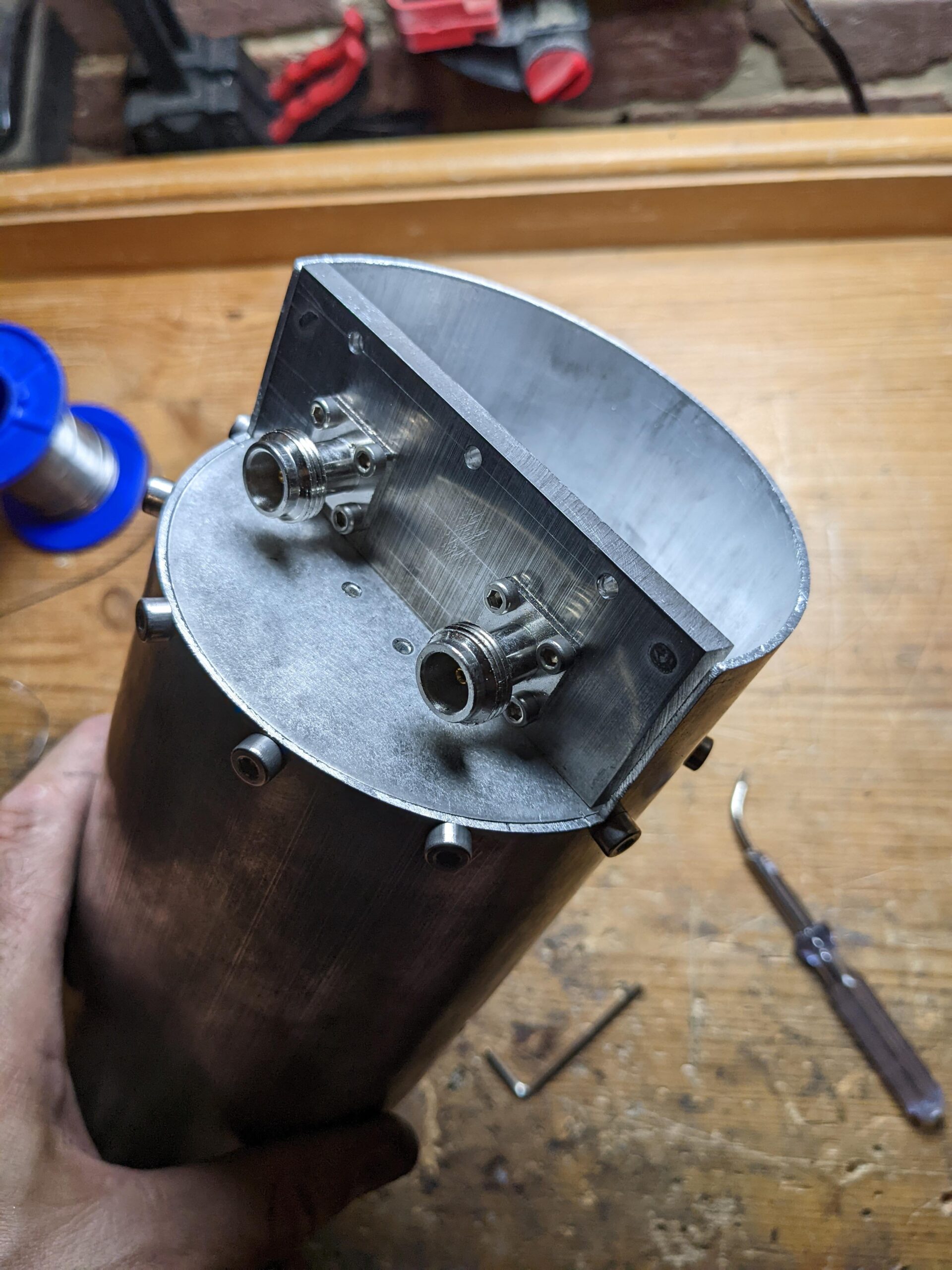
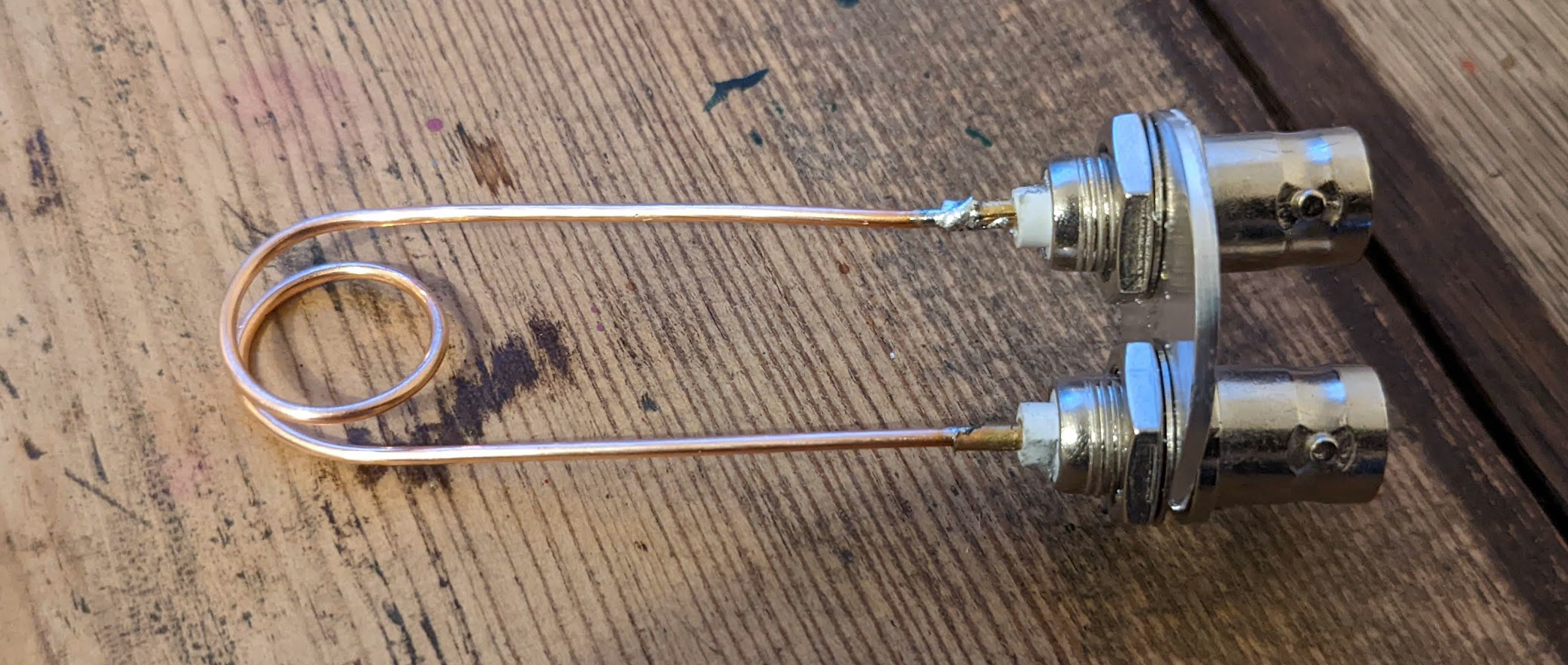
Item 11 – [AL100] – Coupling Loop Bar RX
Item 21 – [AL100] – Teflon Grommet
Items 12, 13, 14, 15, 16, 17, 18, 19, 20 – no drawings required
.
.
Assembly drawing for TX Cavity:
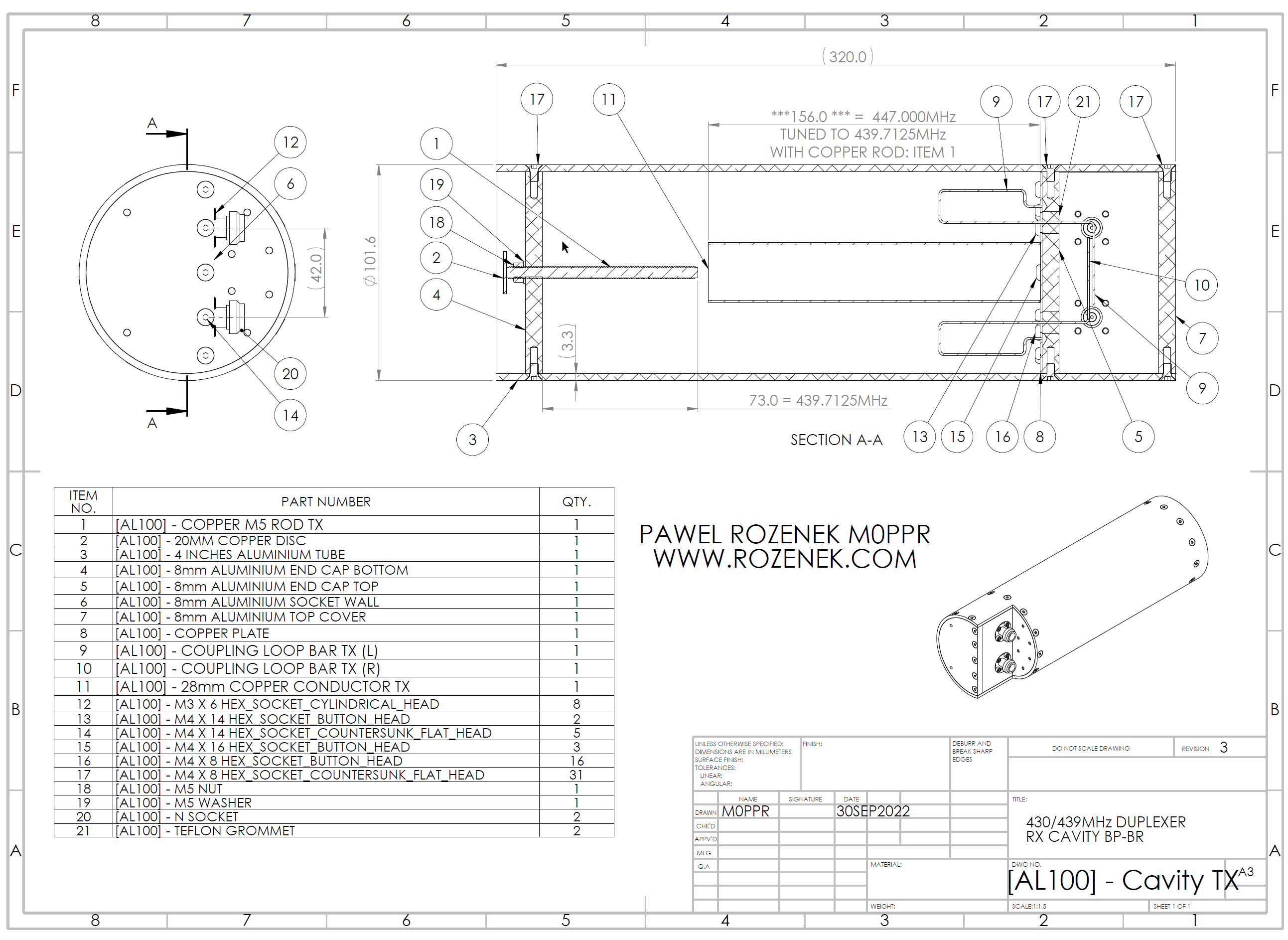
Item 1 – [AL100] – Copper M5 Rod TX
Item 2 – [AL100] – 20MM Copper Disk
Item 3 – [AL100] – 4 Inches Aluminium Tube
Item 4 – [AL100] – 8mm Aluminium End Cap Bottom
Item 5 – [AL100] – 8mm Aluminium End Cap Top
Item 6 – [AL100] – 8mm Aluminium Socket Wall
Item 7 – [AL100] – 8mm Aluminium Top Cover
Item 8 – [AL100] – Copper Plate
Item 9 – [AL100] – Coupling Loop Bar TX (L)
Item 10 – [AL100] – Coupling Loop Bar TX (R)
Item 11 – [AL100] – 28mm Copper Conductor TX
Item 21 – [AL100] – Teflon Grommet
Items 12, 13, 14, 15, 16, 17, 18, 19, 20 – no drawings required
FULLY COPPER TEST CAVITY – 10dB better notch attenuation but assembly process was disaster!!!
* My first test cavity was turned using a grinder and a metal file!!!!!!!:
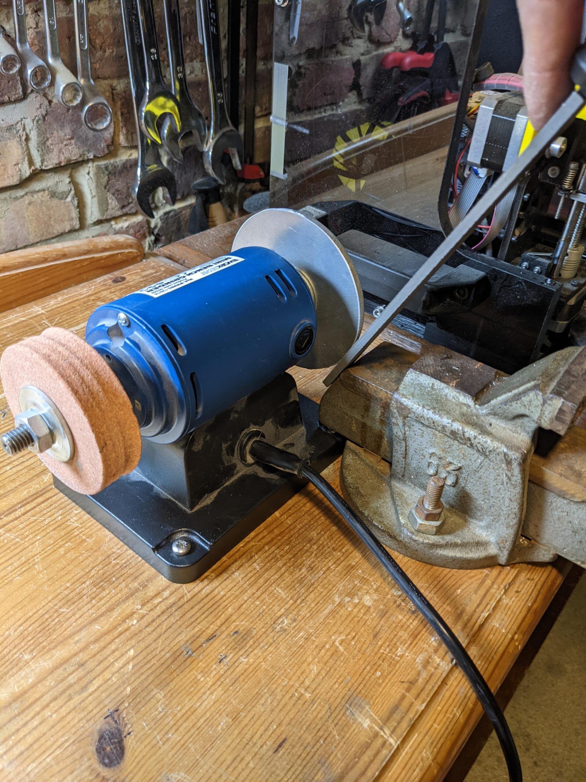
the second one was turned using a pillar drill as a lathe!!!!!
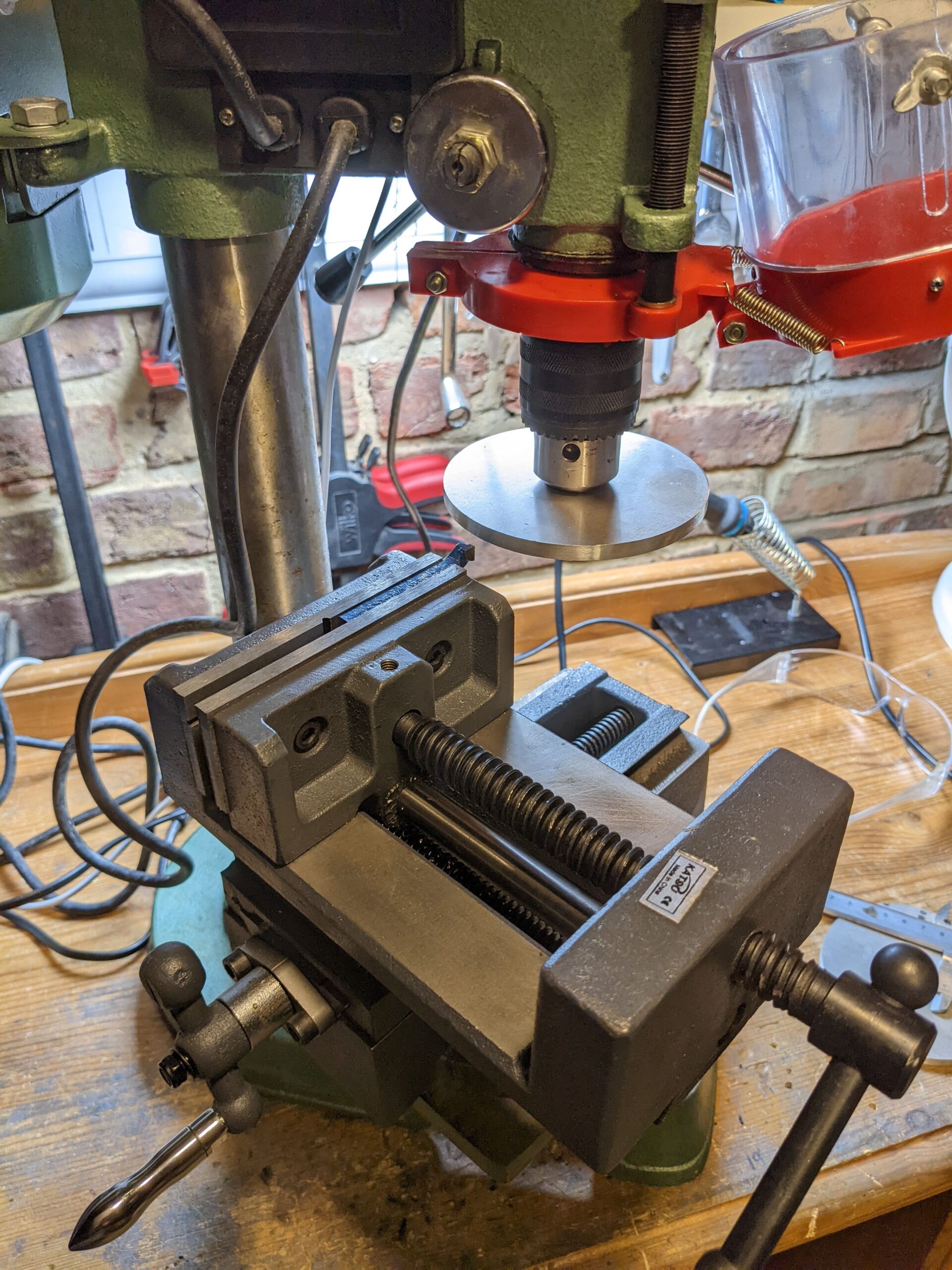
However finally I decided to invest some money and get a mini lathe:
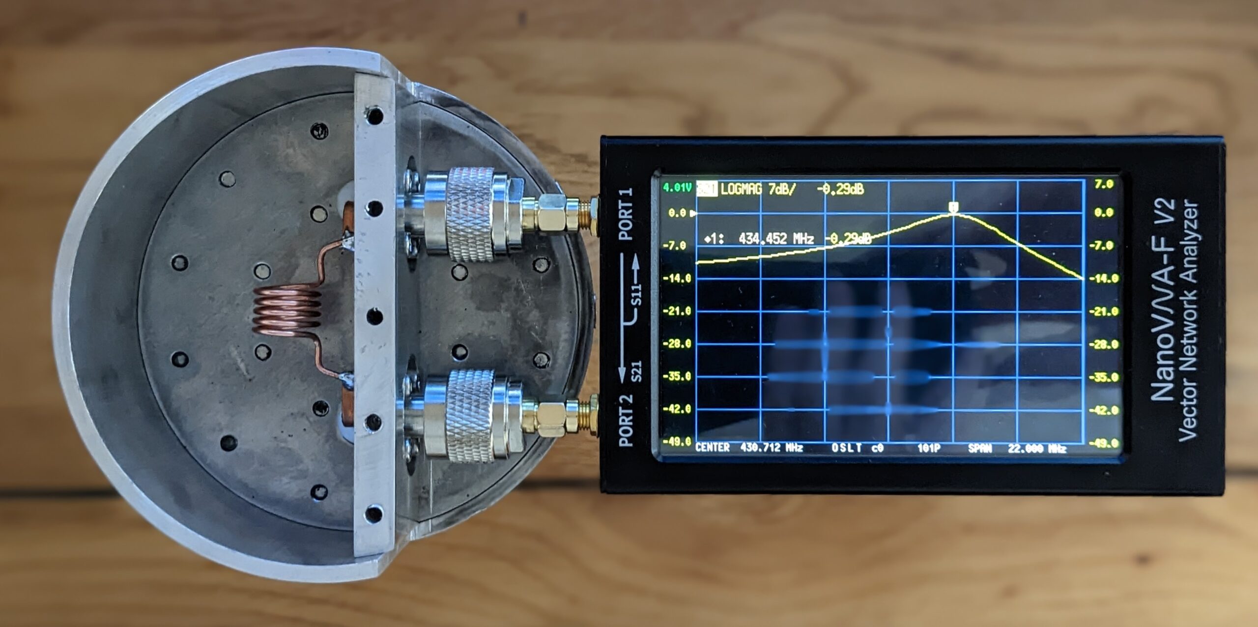
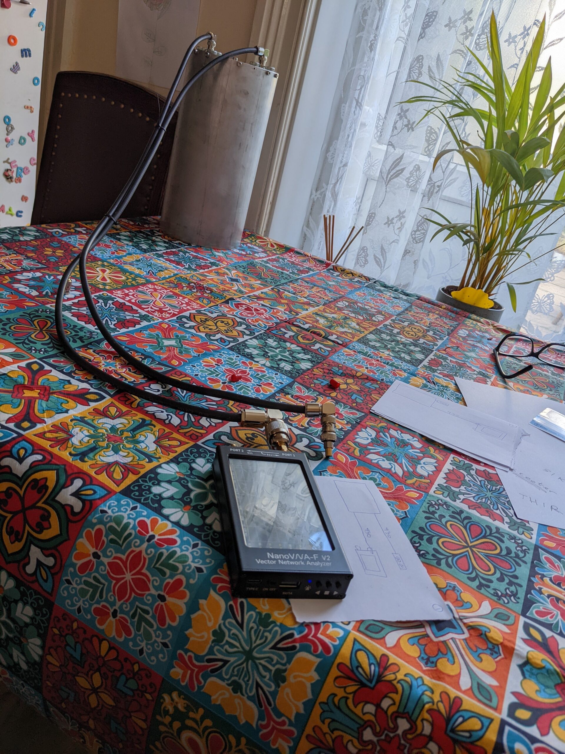
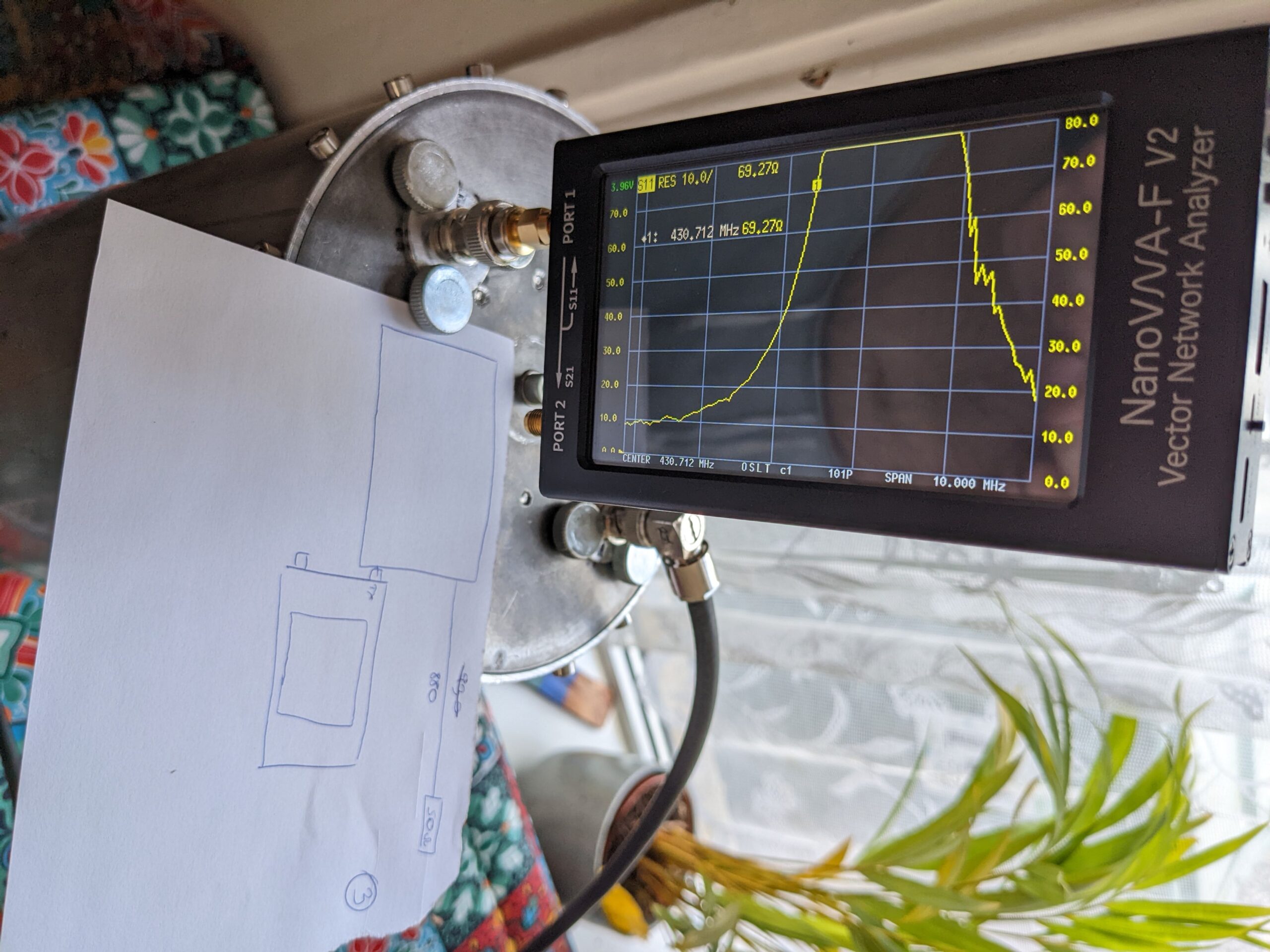
** You do not have to spend £1000s on the spectrum analyser. Nano VNA will do the job perfectly, however the noise level for it is 70dB so no chance to measure entire duplexer’s parameters, but it will be good enough to measure every individual cavity and the total SWR – which will be acceptable.
ANYTHING BELOW IS NOT OBLIGATORY TO READ IF YOU WANT TO MAKE YOUR OWN DUPLEXER. HOWEVER IT IS A BIT OF THE HISTORY HOW I LEARNT ABOUT DUPLEXERS AND WHAT MISTAKES I DID 🙂 THERE IS ALSO A BIT OF THEORY TOO WHICH WILL BE HELPFUL IF YOU WANT TO UNDERSTAND WHAT AND WHY YOU MAKE!!!
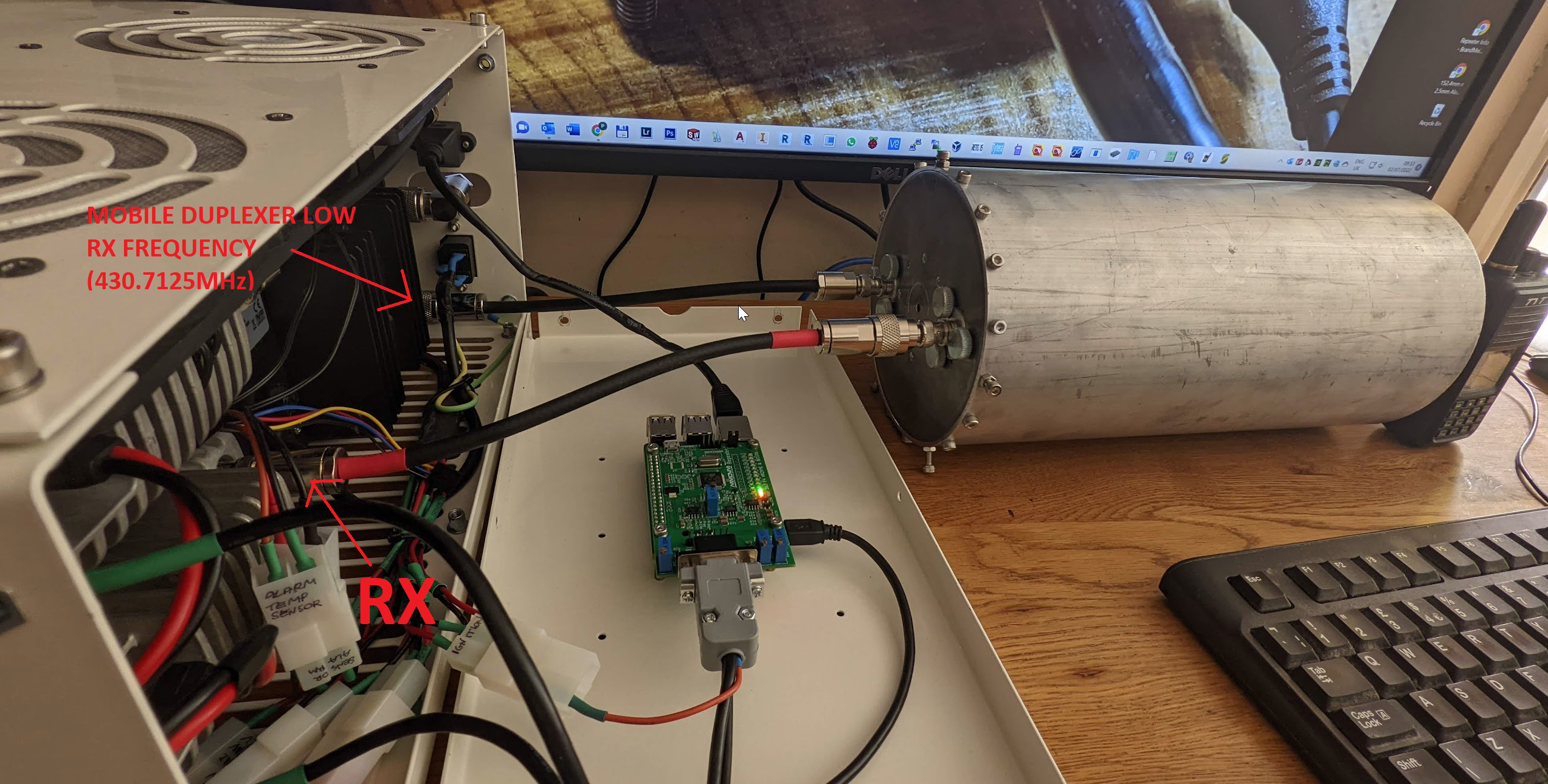
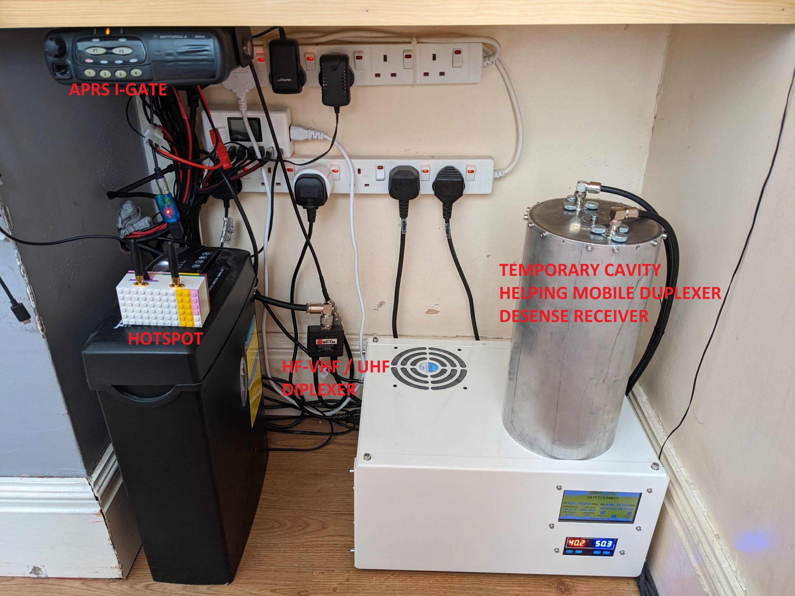
First of all – a short story why I decided to make a test duplexer myself. I am the owner of two amateur DMR repeaters. They both use a cheap Chinese mobile duplexers:
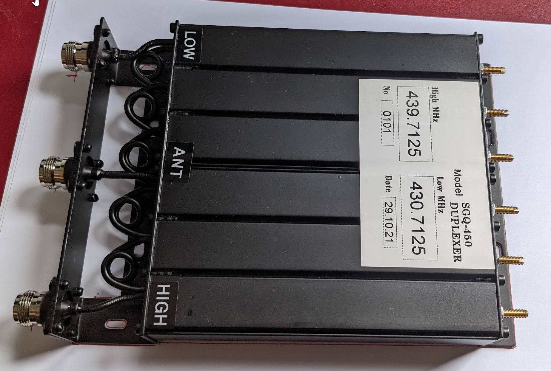
Despite the fact that the manufacturer sent me quite a promising spectrum analyser results the duplexer does not work very well.
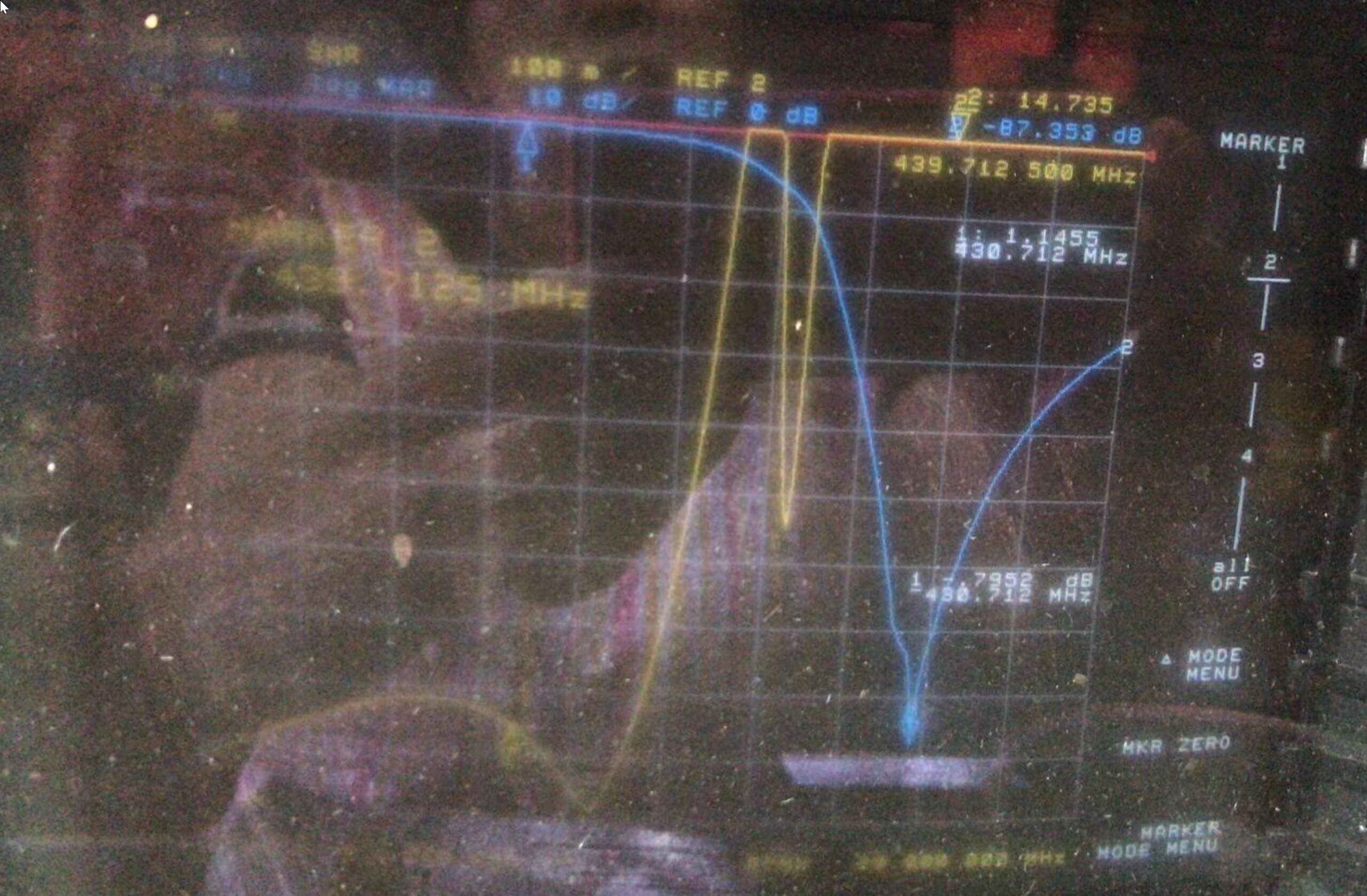
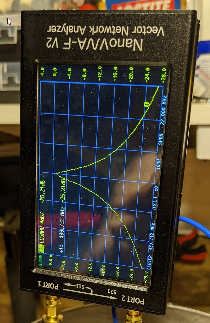
All calculations below are based on repeater’s TX: 439.7125 and repeater’s RX: 430.7125 (9MHz offset).
Your radio RX: 439.7125, your radio TX: 430.7125
When the TX starts transmitting with 10W the receiver desenses quite badly. After reducing the power to just 1W the repeater started to be a bit more usable, however 1W is NOT a lot. At the edge of the repeater coverage I still had to use about 40W to get into the repeater’s receiver, so the disproportion between the repeater and my mobile radio was massive! Repeater: 1W, mobile radio: 40W!!!
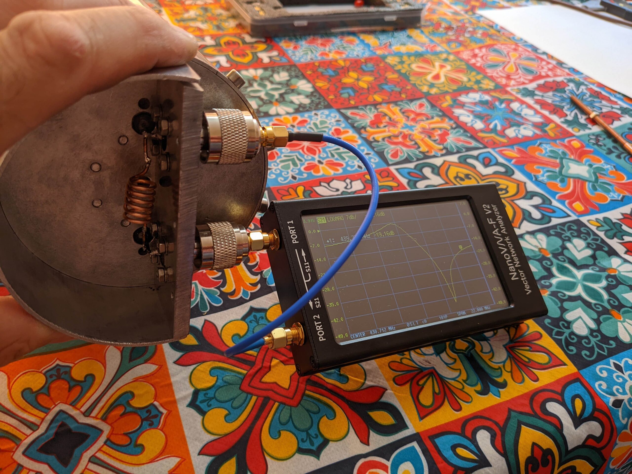
The option was to TRY to retune the duplexer, however the only one device I have is a nanoVNA spectrum analyser. It is what you pay for – a very useful but also a very limited device. When you tune duplexers you operate with signals like -80…-100dB. NanoVNA starts generating noise at the level of 70…80dB which makes tuning mobile duplexers not very precise!
Also it was difficult to establish if the desensing problem is created by a the TX’s noisy spurious emission or the RX selectivity is not great despite almost 90dB separation from TX. I assumed the problem was with the not adequate separation. At the time I started to think about making my own duplexer cavity I had had no experience at all with duplexers. So first of all I decided to spent a week to keep reading about duplexers. After a week I was able to order some material to make a SINGLE TEST bandpass cavity. My plan was to add extra separation by adding the extra cavity between the receiver and the mobile duplexer.
For impatient people I present exact dimensions of the cavity I fabricated. After that you will see some theory about making duplexers – so it will help you to modify the design to suit your own requirements.
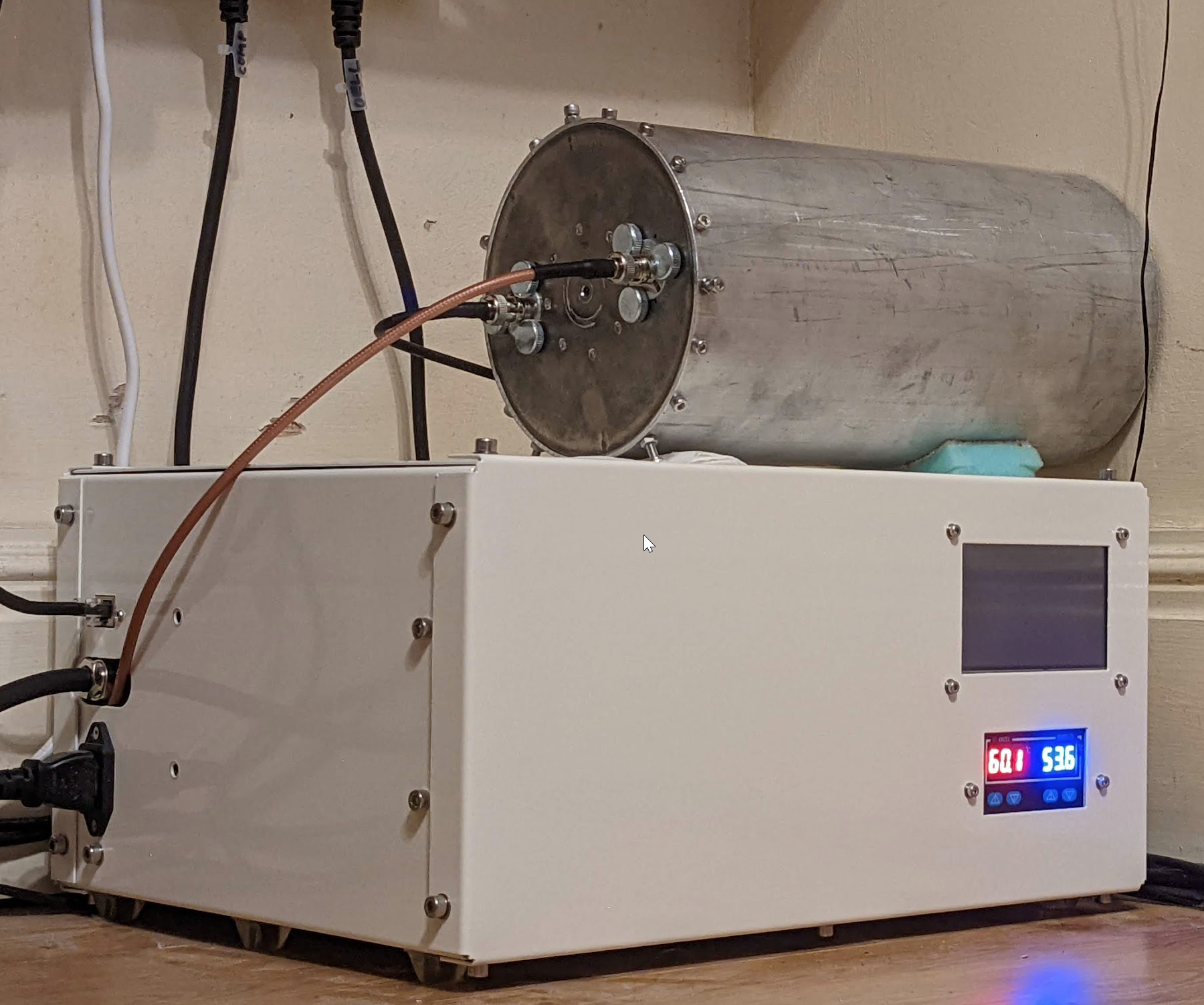
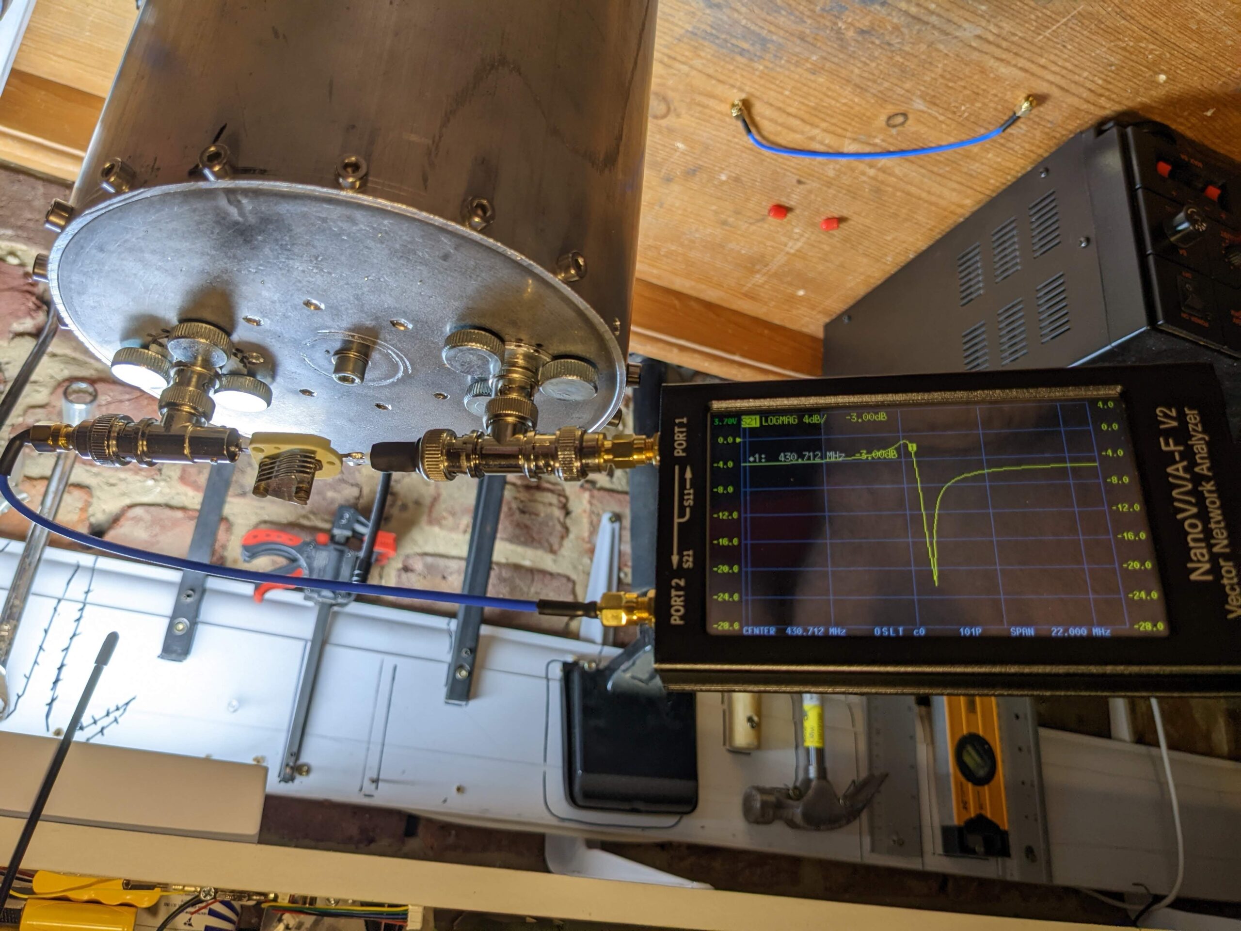
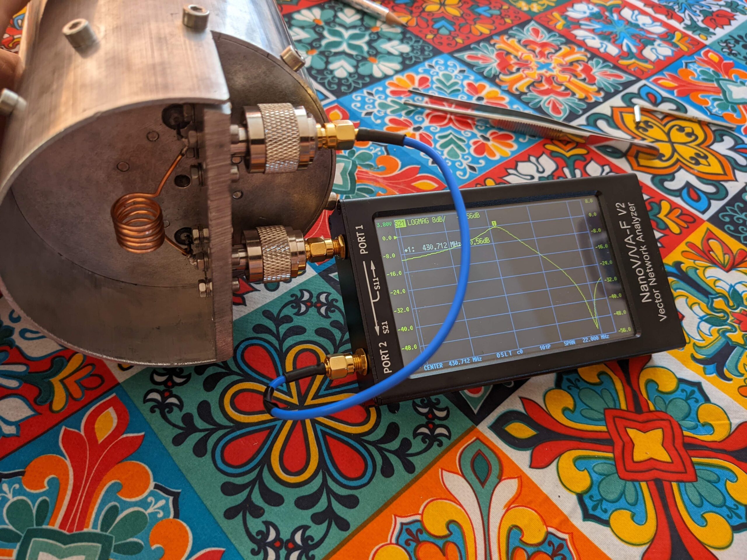
The duplexer attached to the repeater’s enclosure:
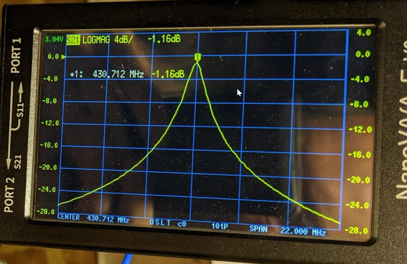
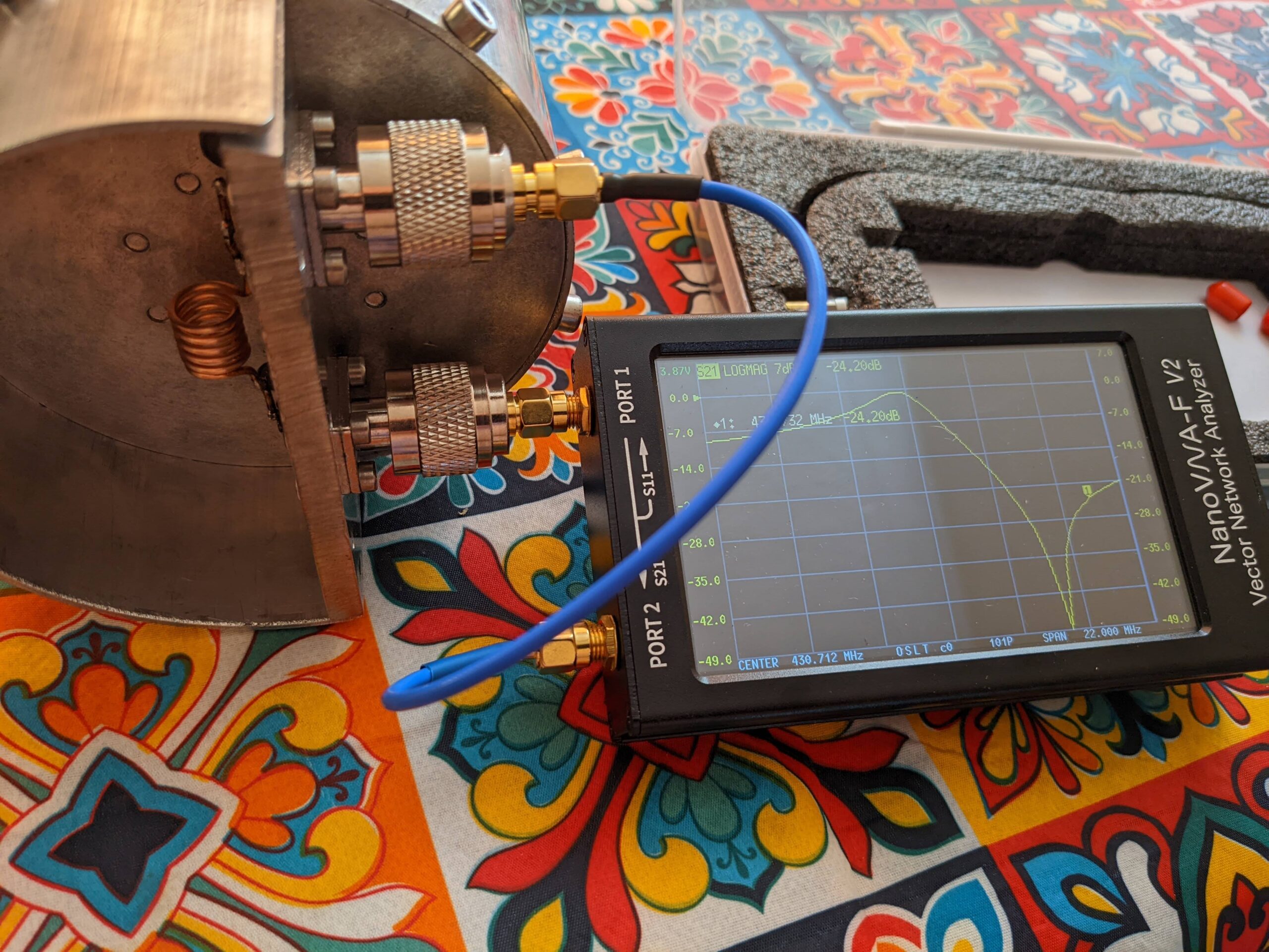
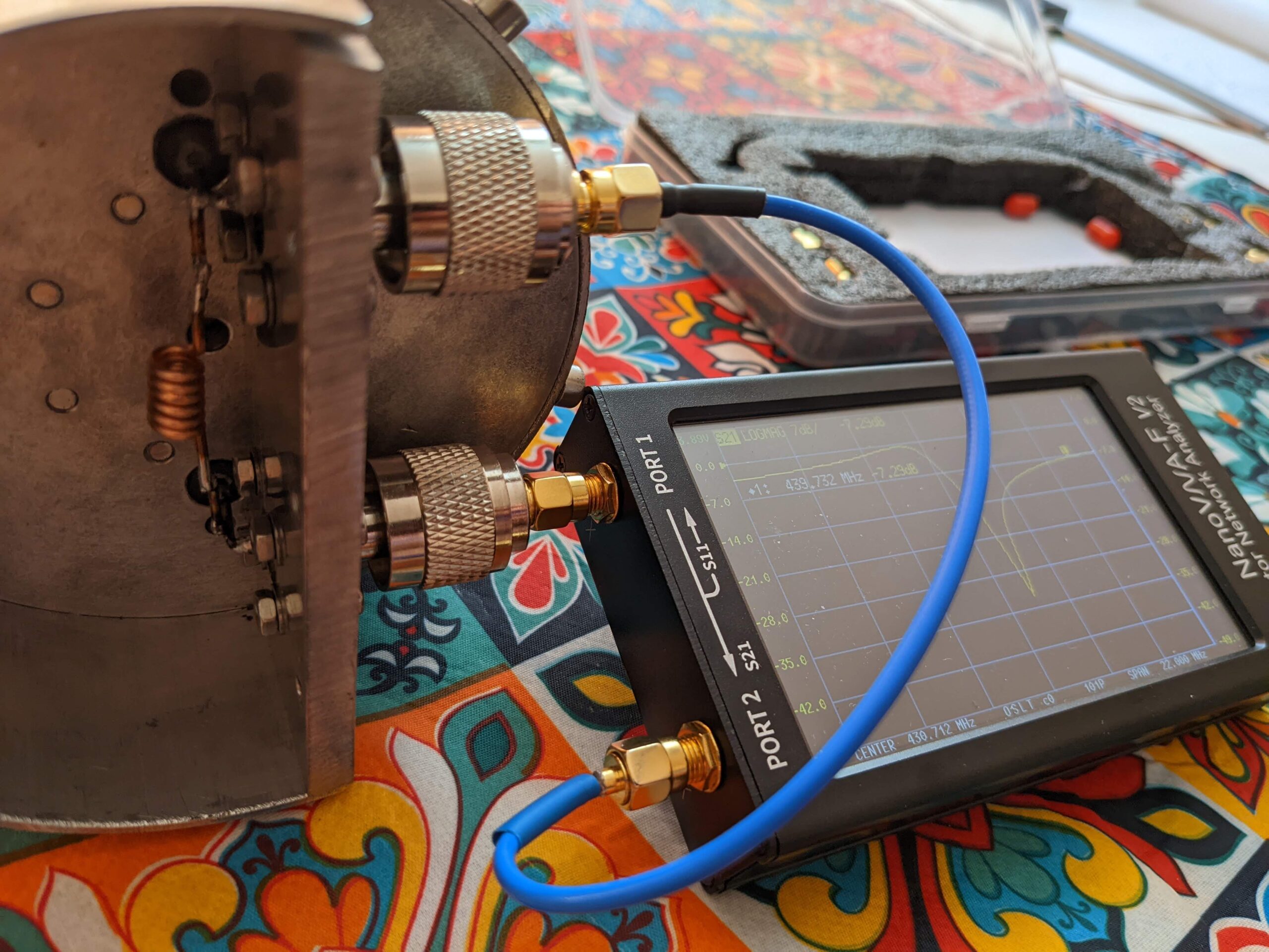
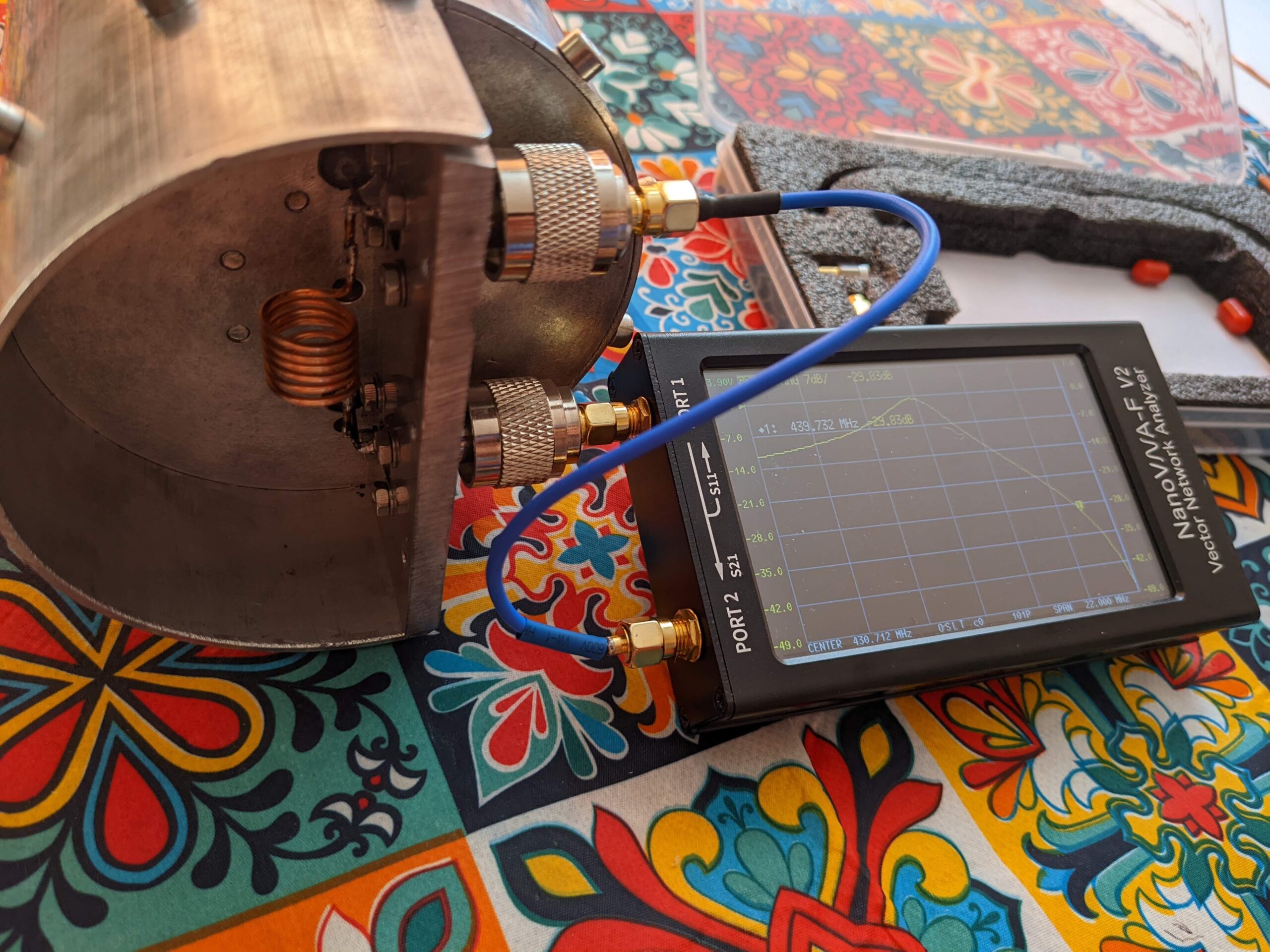
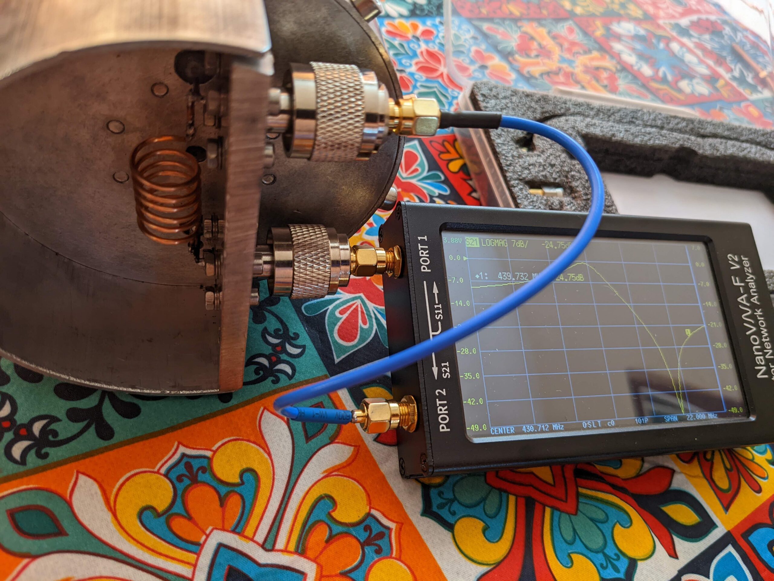
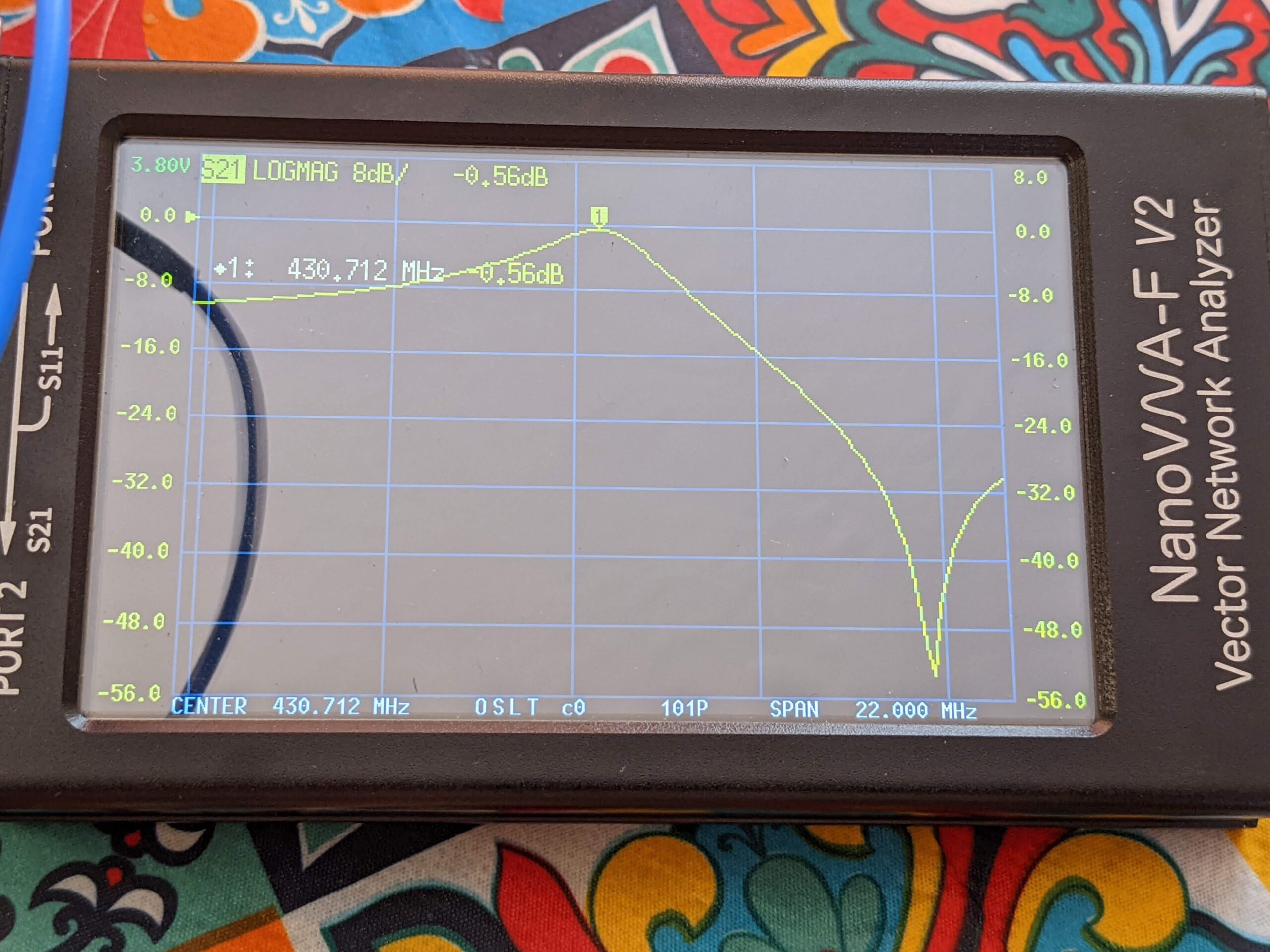
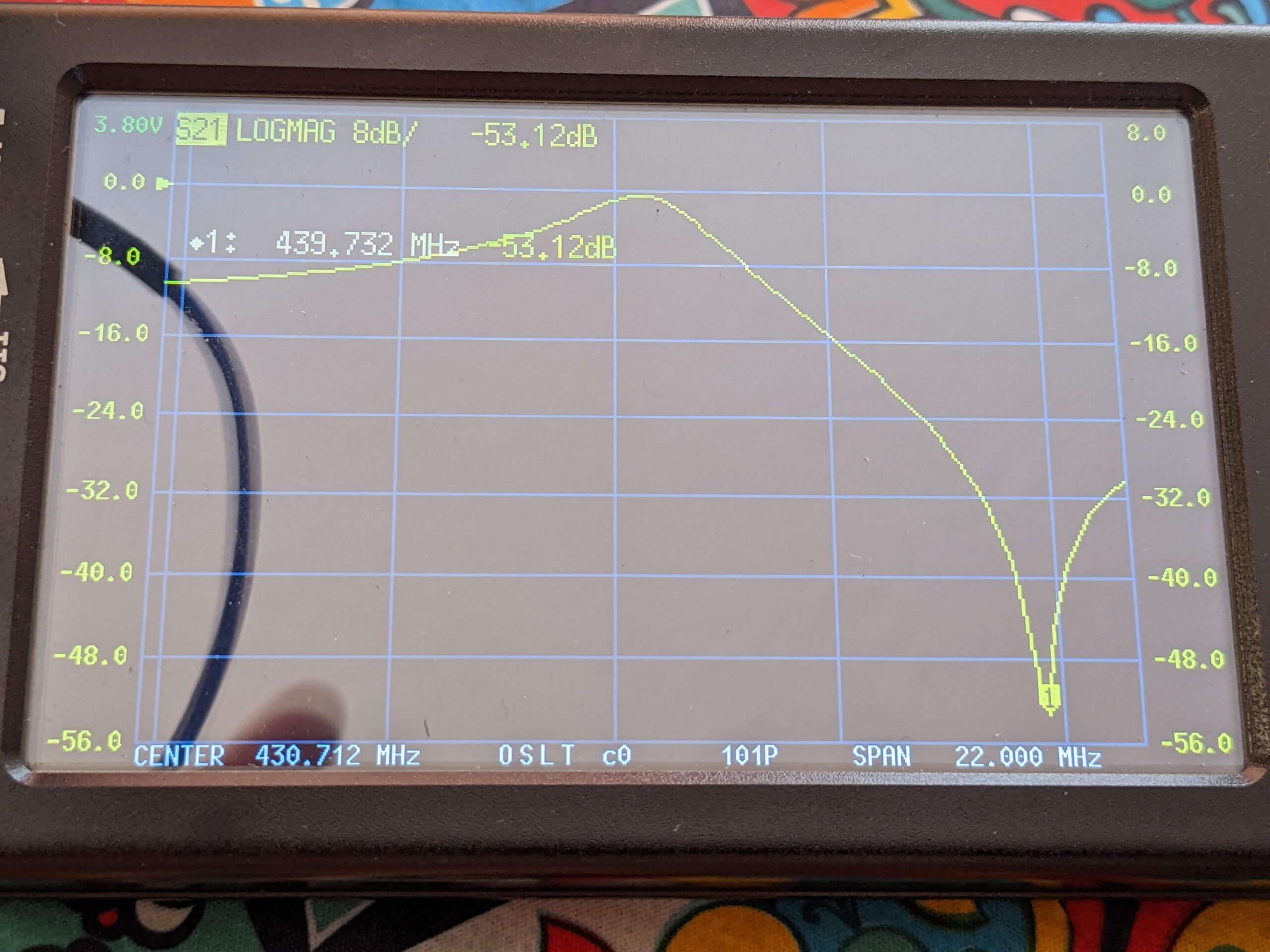
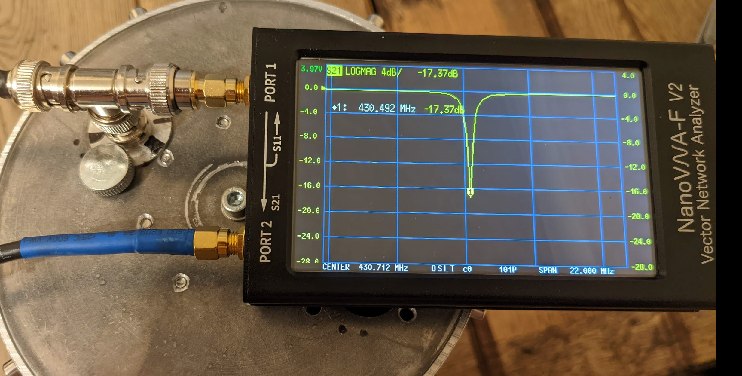
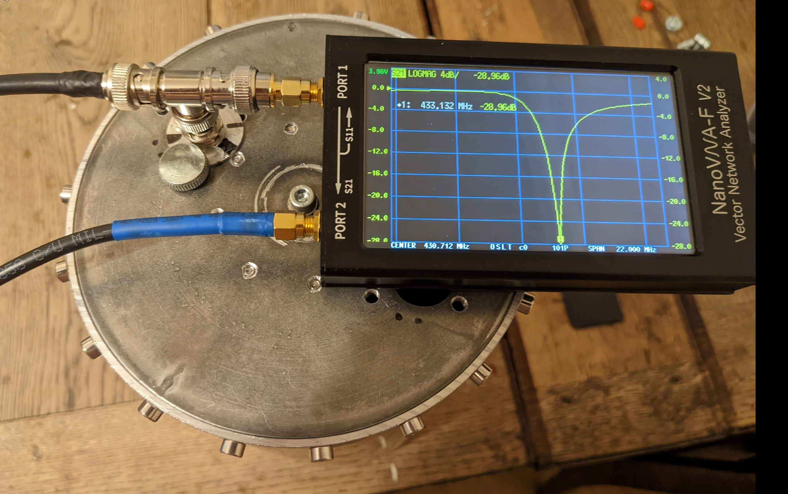
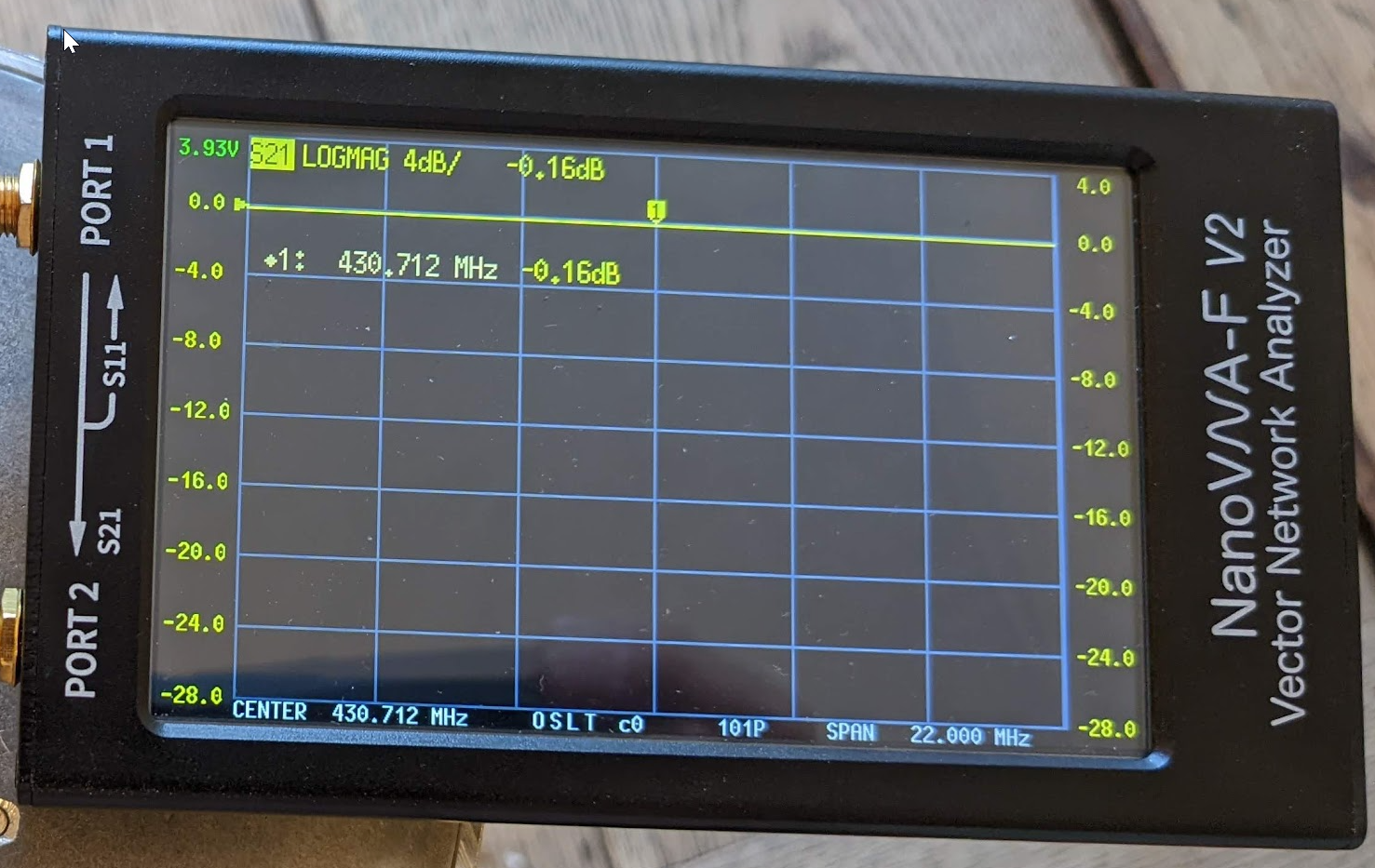
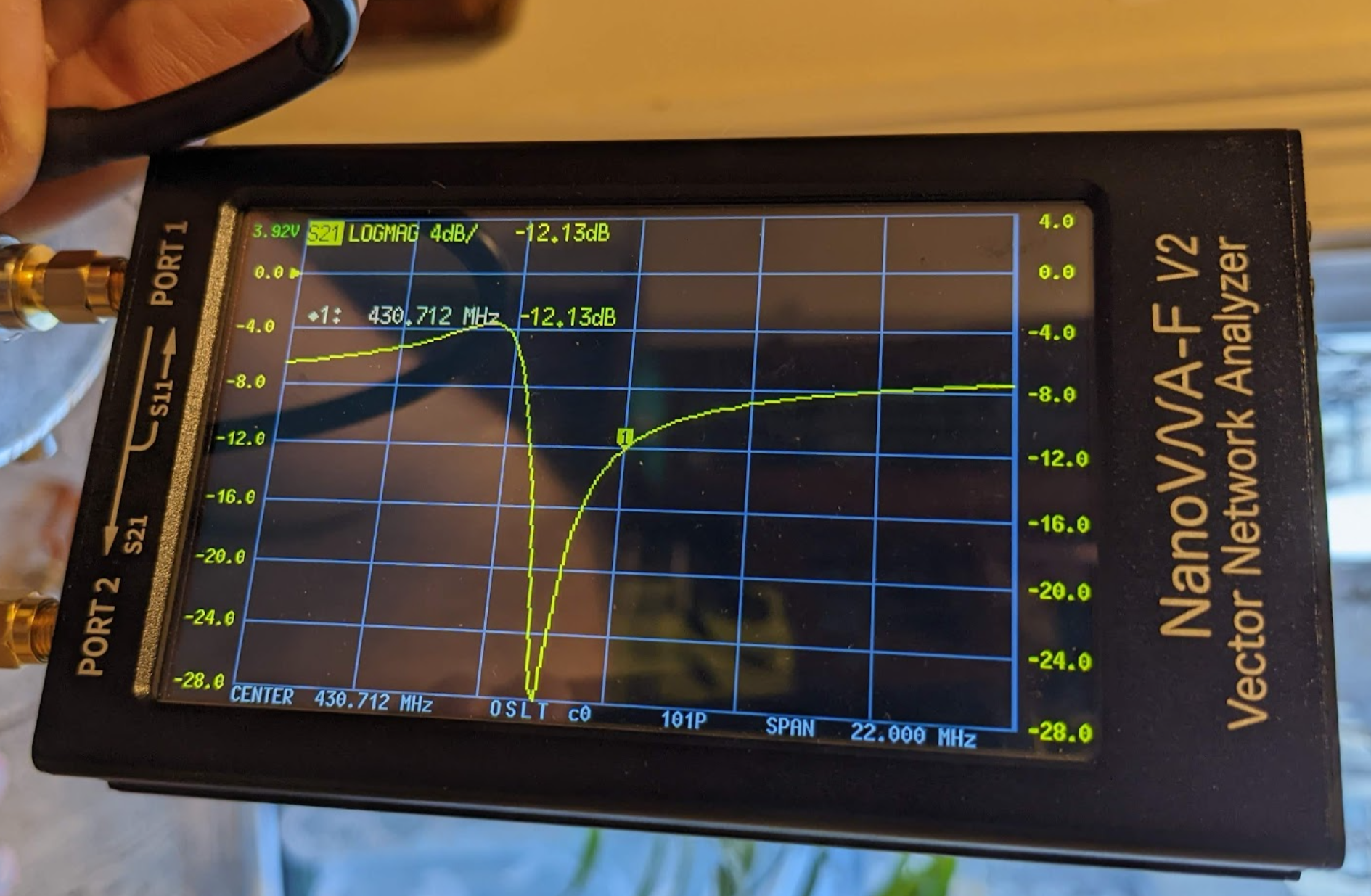
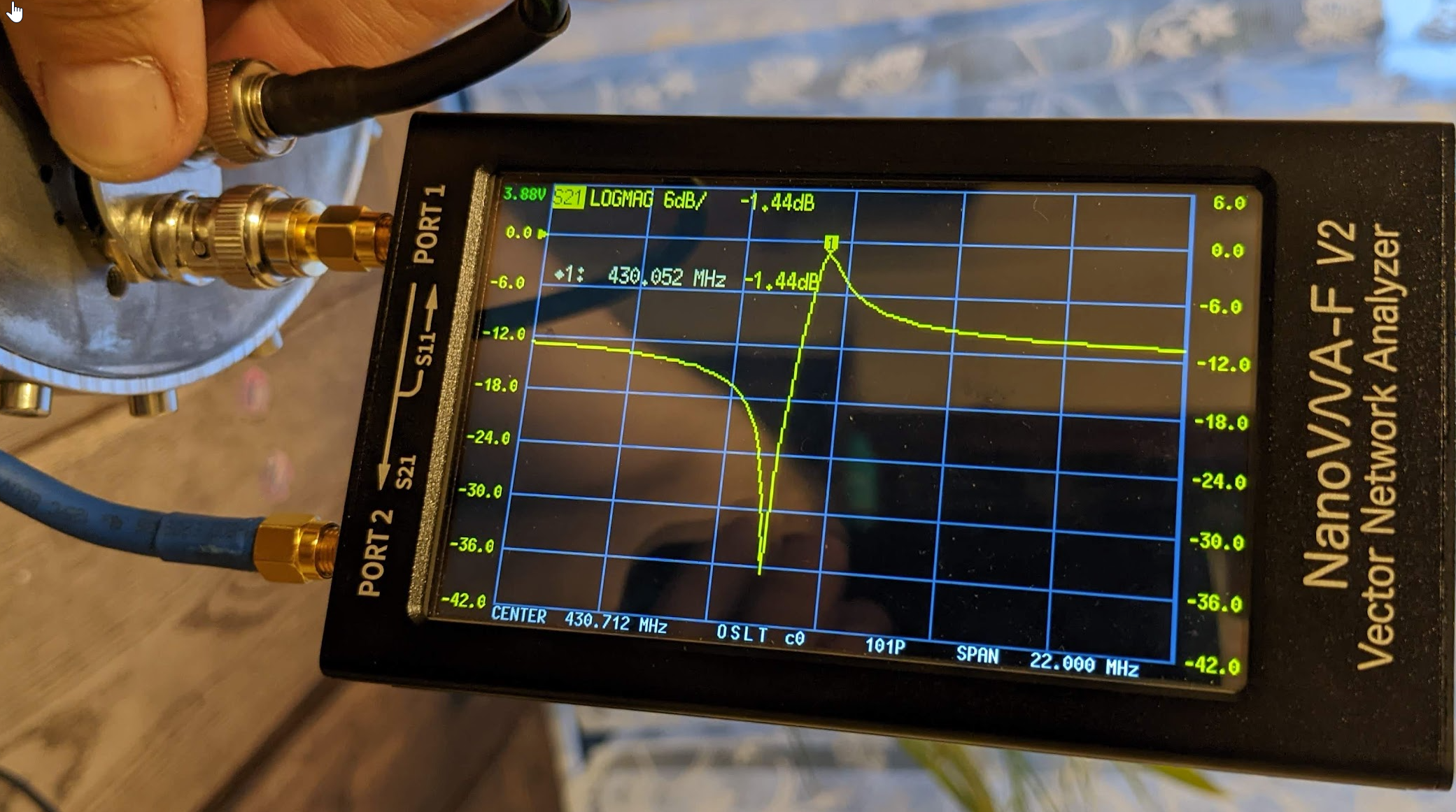
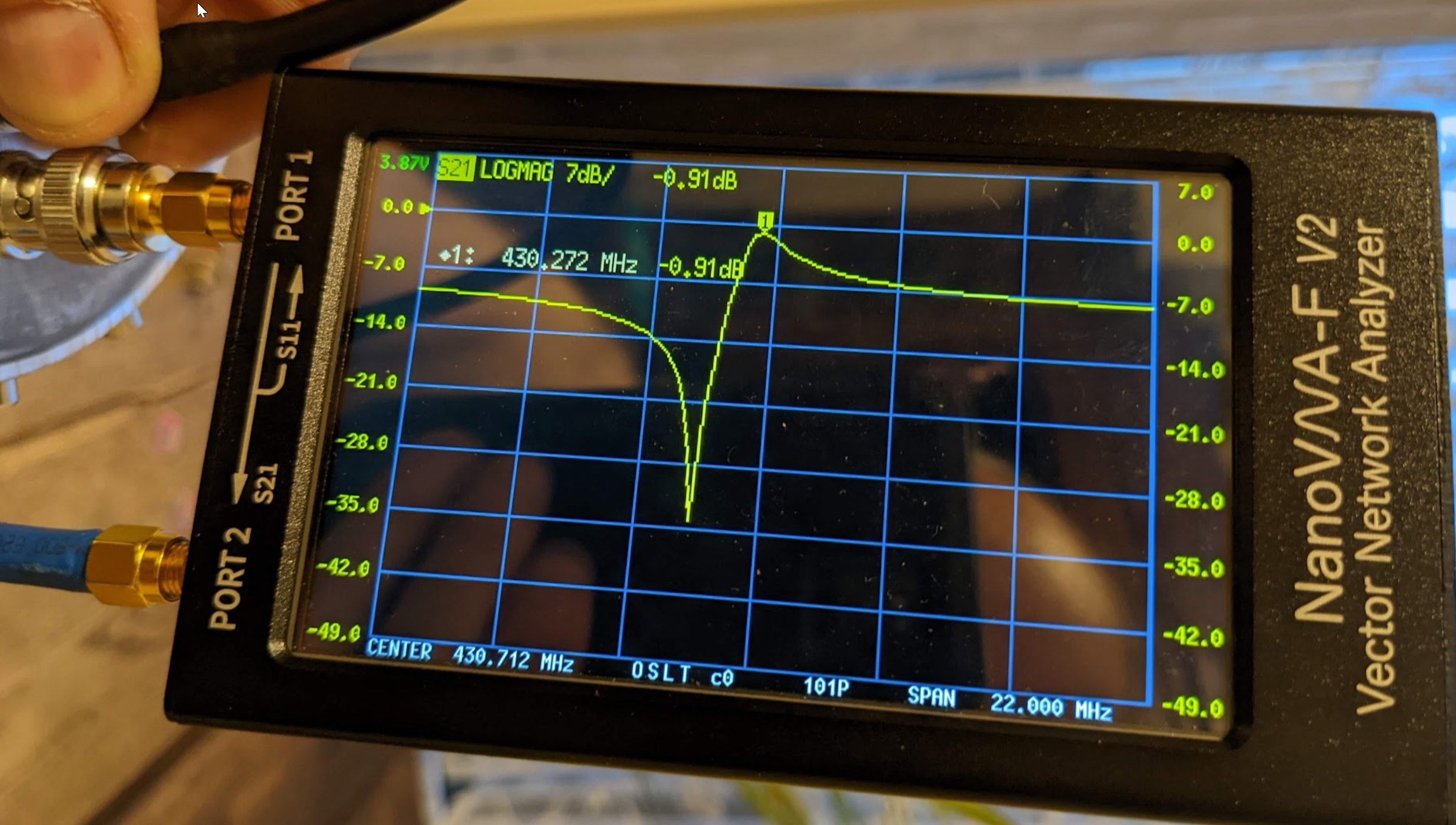
Results of the extra single cavity are shown below:
If you further scroll down you will find the theory about coupling loops, but generally the lowest looses I achieved were only 0.35dB but the separation was only about 10dB. So the cavity would virtually reduce the 10W TX power to 1W. Not a great result. The other option was to rotate slightly the cavity coupling loops and with 1.16dB looses the separation was 25dB! It is like reducing the TX power from 10W to 0.03W = 30mW!!! Amazing! Now I can transmit 10W RF power from my repeater with no problems at all! And now, practically, if I go away from the repeater to the edge of the repeater’s reception, I need to transmit 5W…10W to get into it. So the repeater and mobile stations are now quite well balanced. Previously, because of the desensing problem the repeater was transmitting 1W and mobile station had to transmit 40W!
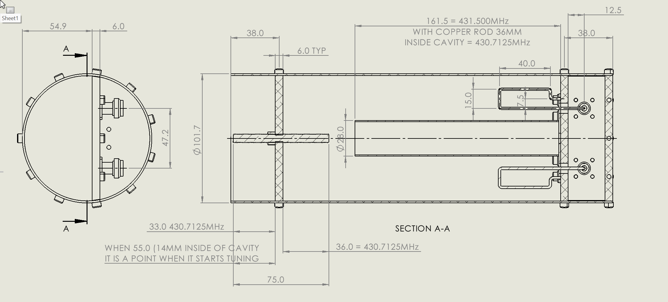
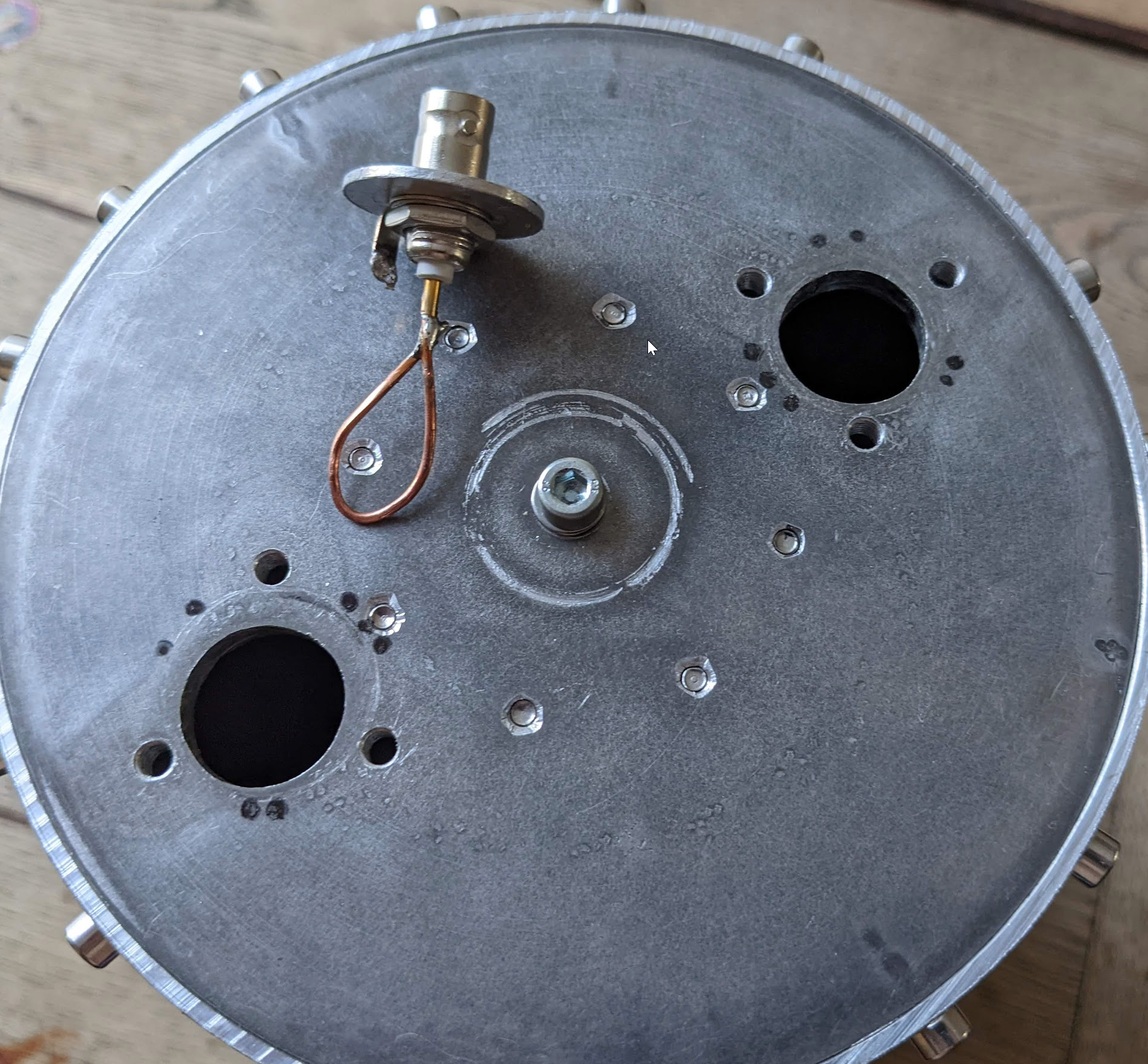
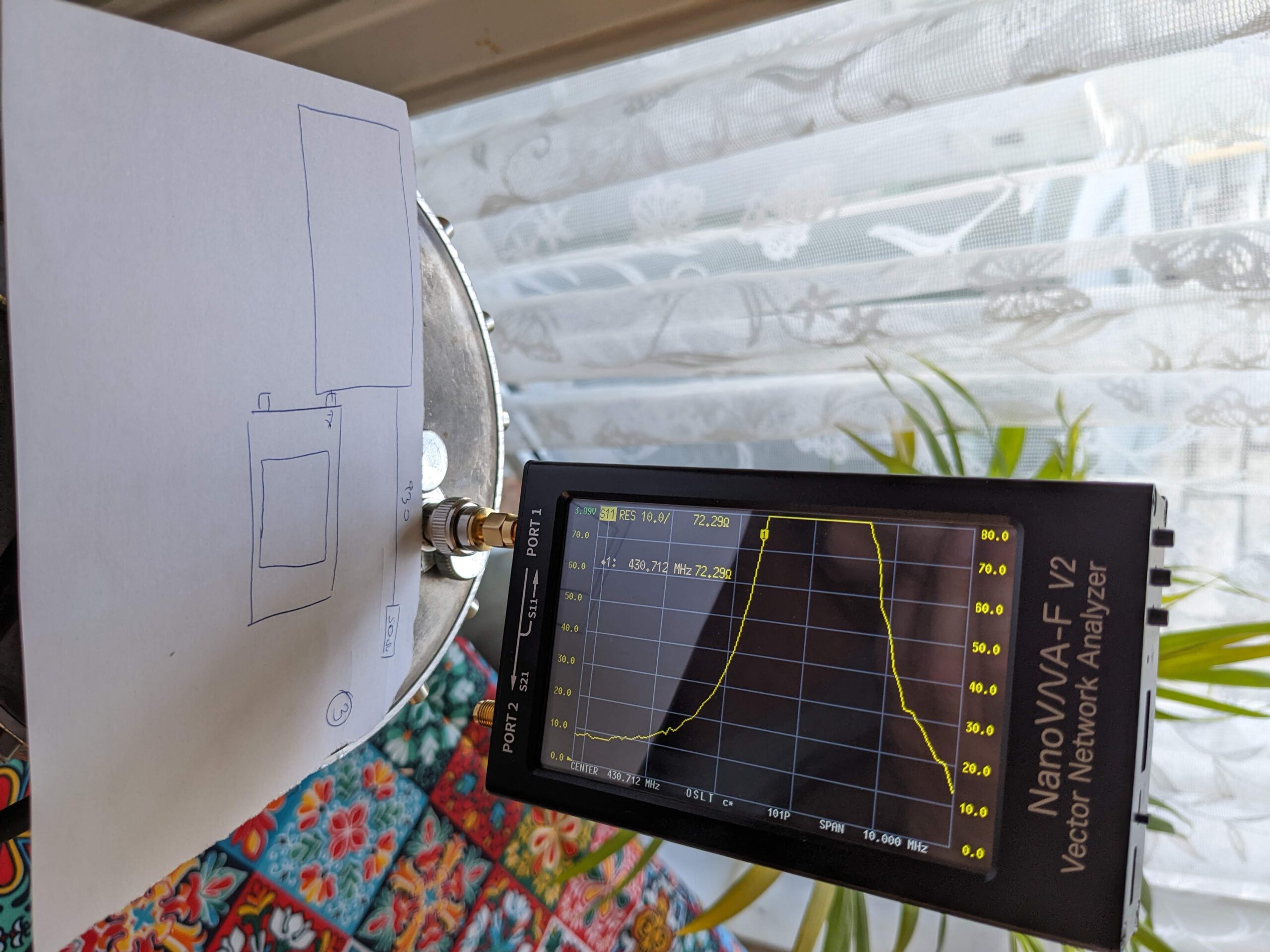
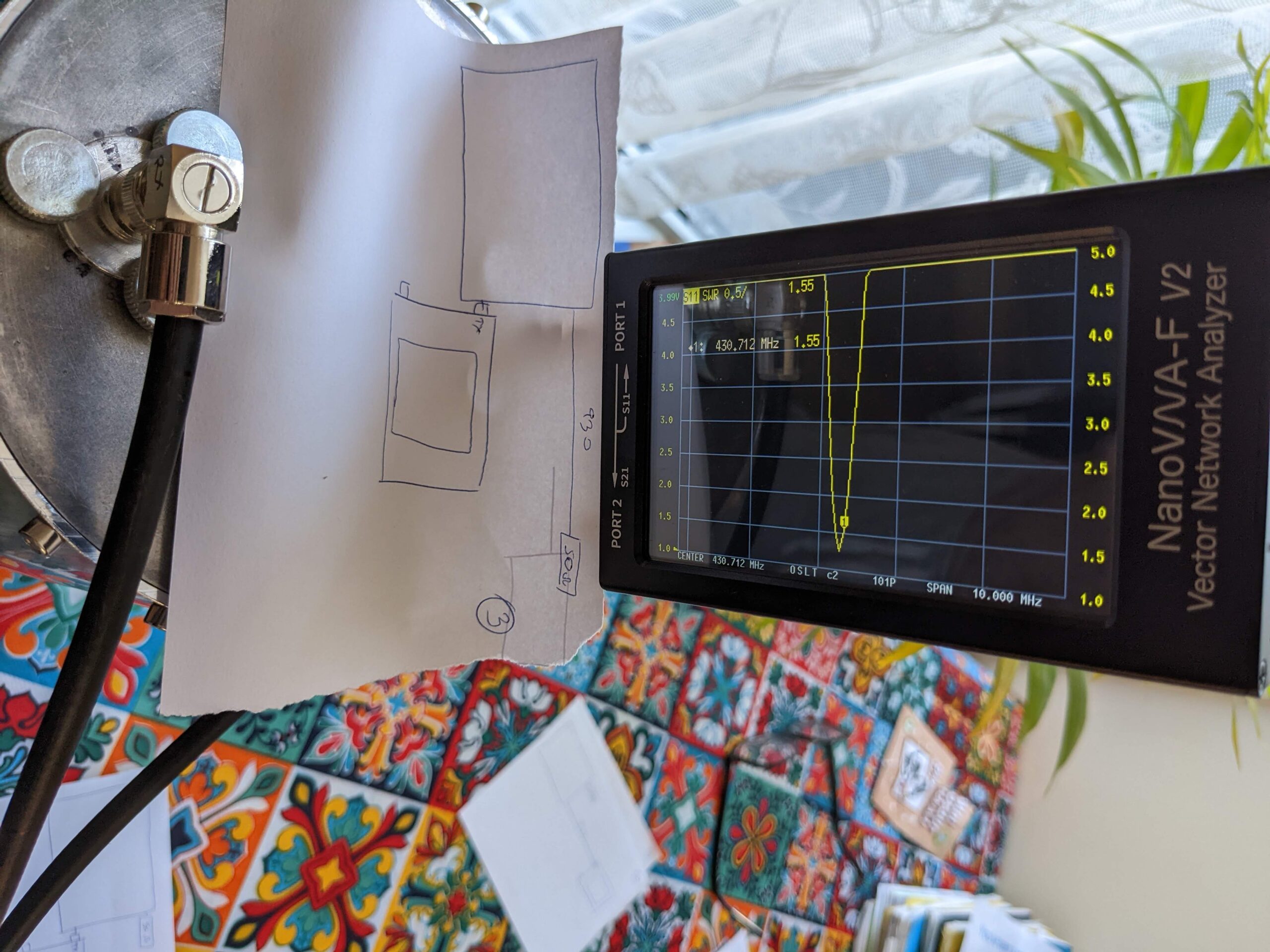
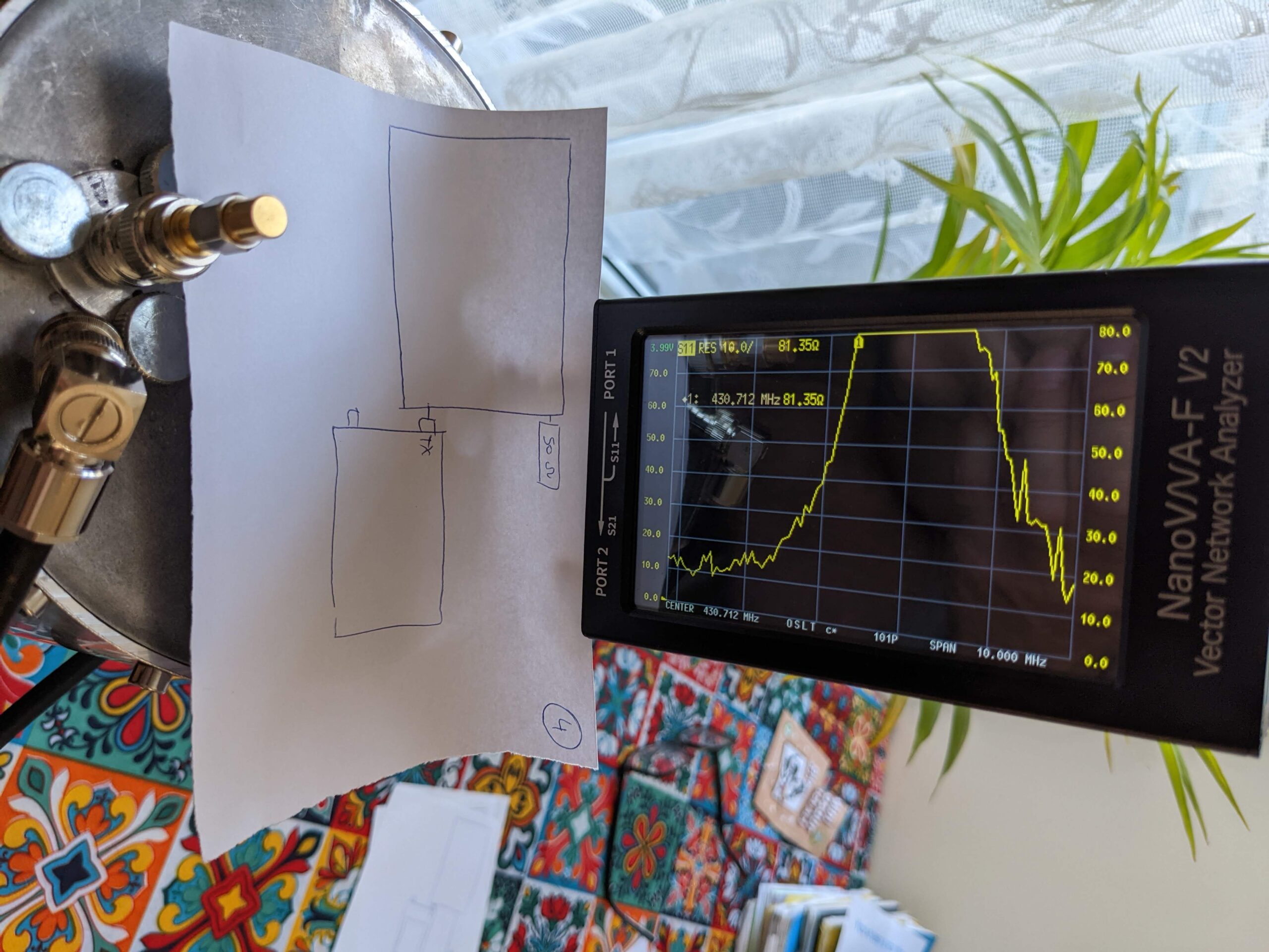
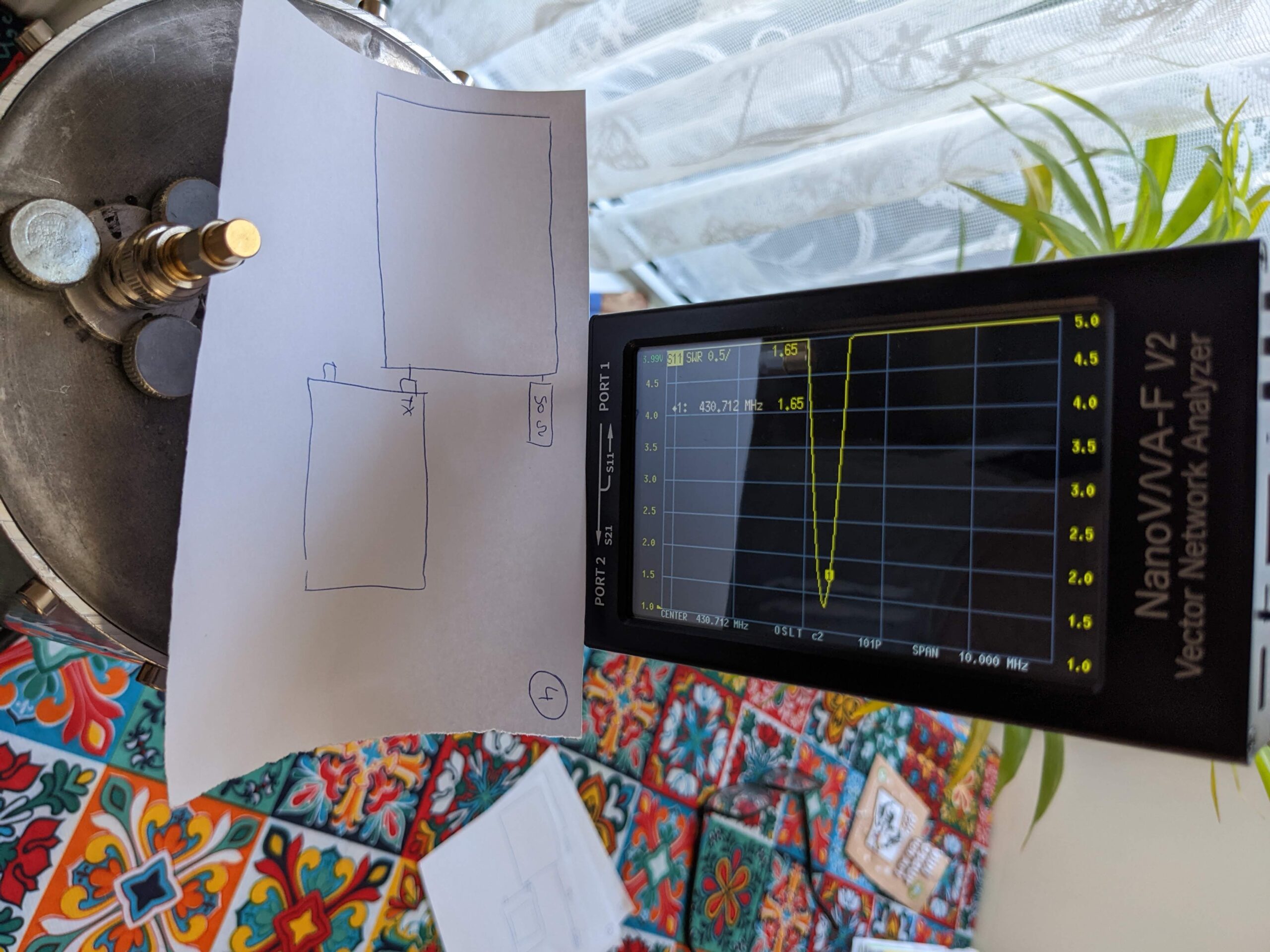
Construction of the cavity:
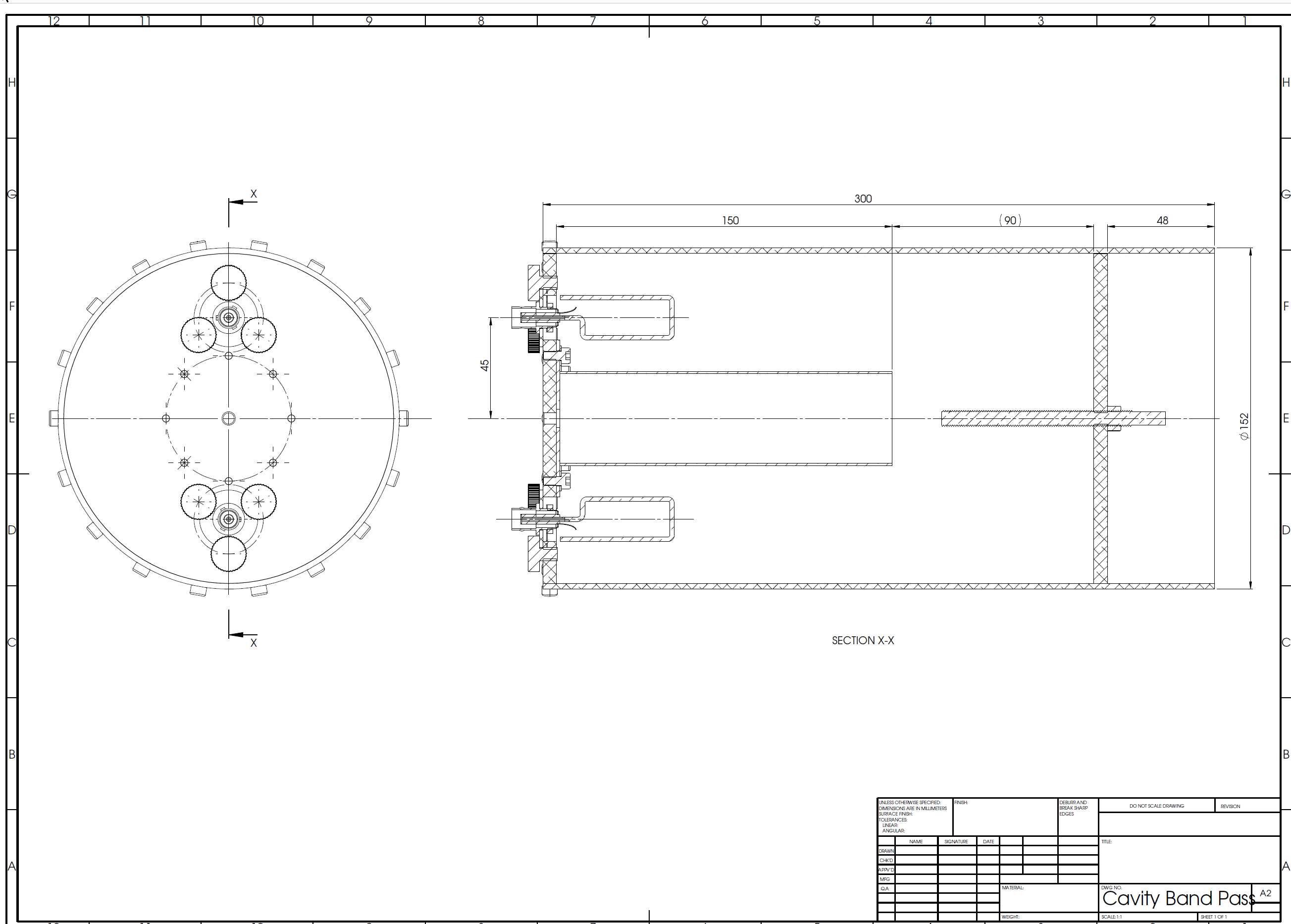
More drawings to follow!! The drawing above shows a idea of the cavity for 430.7125MHz
Total length is 300mm, diameter 6 inches (152mm OD), the centre resonator diameter is a copper OD 42mm and 150mm long. Without the extra tuning rod added to the end plate the cavity with 150mm long centre resonator tuned to 435.7MHz. My desired frequency for RX is 430.7125 so I think I chopped the tube a bit too much – that’s why I had to have a 68mm long copper M6 rod to add extra capacity which decreased the centre frequency form 435.70000MHz to 430.7125MHz. I think the perfect length to tune just a little bit above require frequency eg. 431.0000MHz could be around 152mm – I predict 152mm resonator could create 431.0000MHz resonance. All because I found that for every 2.3MHz you need to add/reduce 1mm of the resonator’s OD 42mm rod. Or 1 MHz changes the centre rod by 0.43mm. The reason of saying that it would be good to have the centre frequency done to 431.0000MHz where desired one is 430.7125MHz is because by adding the tuning copper M6 rod will keep decreasing the frequency. More you push the M6 tuning copper rod inside of the cavity, more the frequency gores lower (longer wave). It is impossible to tune the other way 🙂
Please note the back end cap is located 90mm away from the end of the centre resonator. This is the minimum distance from the end of the centre conductor where the end cap has got no affect the centre of frequency. If you start DECREASING the distance to get closer to the conductor, the capacity of the system will increase and the centre frequency will move to a lower frequency!
The centre conductor outer diameter is 42mm because 152 : 3.6 =42 🙂 3.6 factor provides the best filtering performance with impedance of 78ohm. Some people use 3.25 factor which is 70 ohms.
With 3.6 factor if you use 100mm tube, the inner conductor diameter should be roughly 28mm
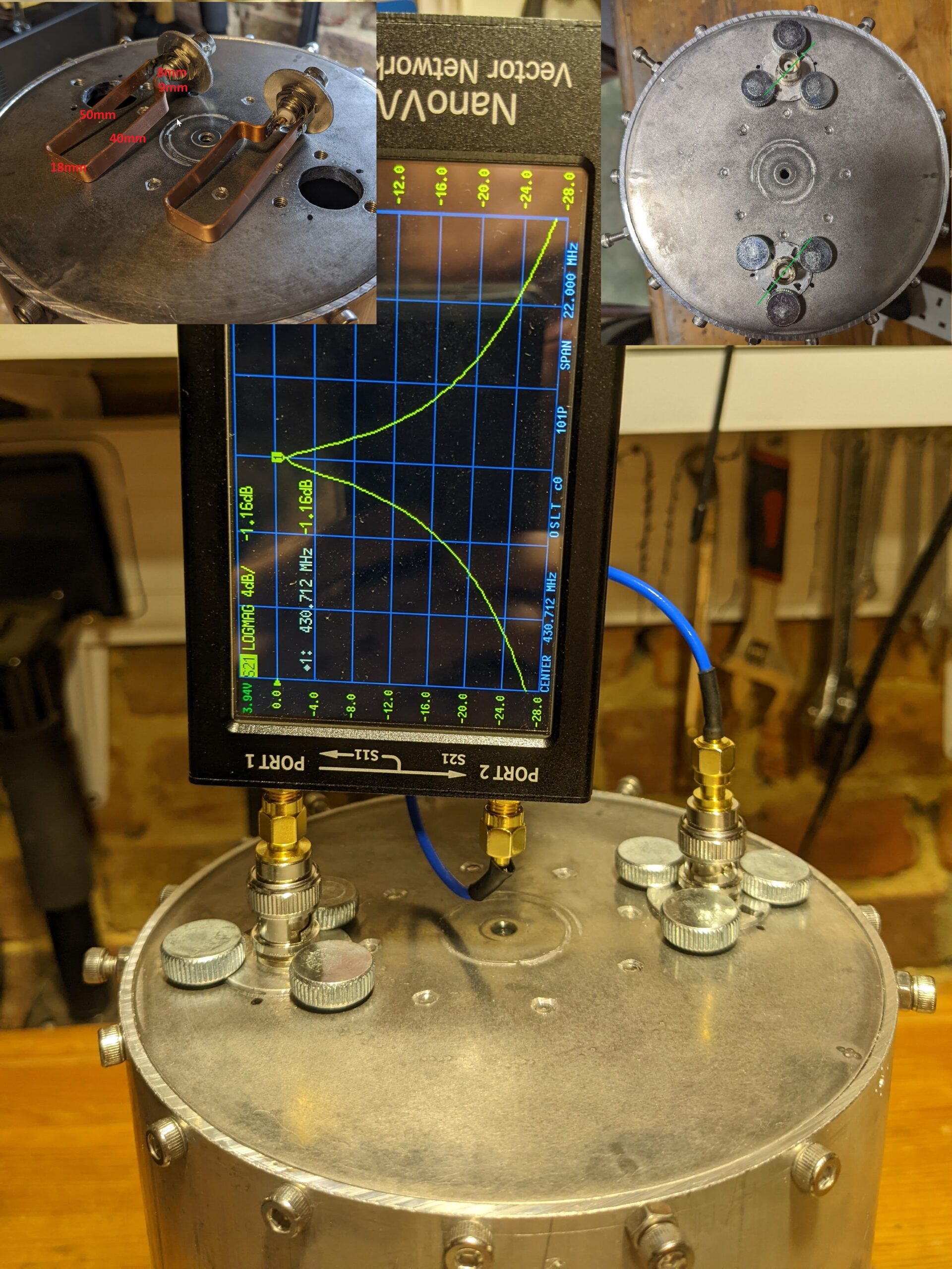
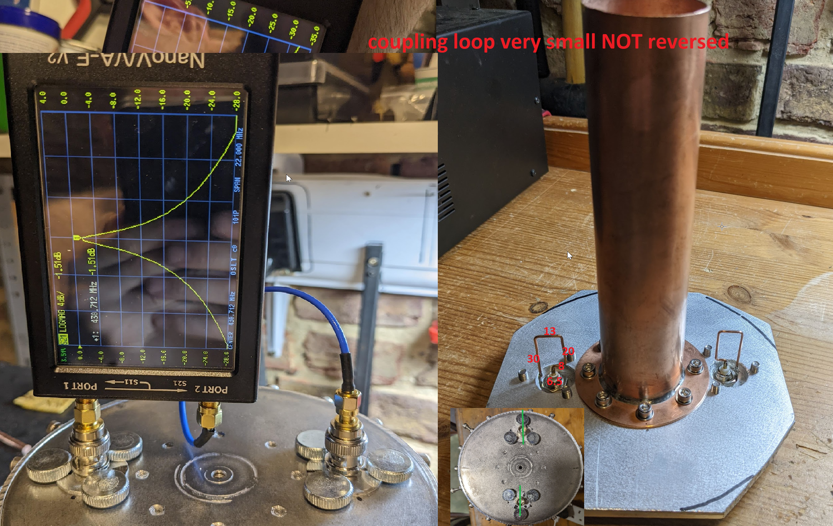
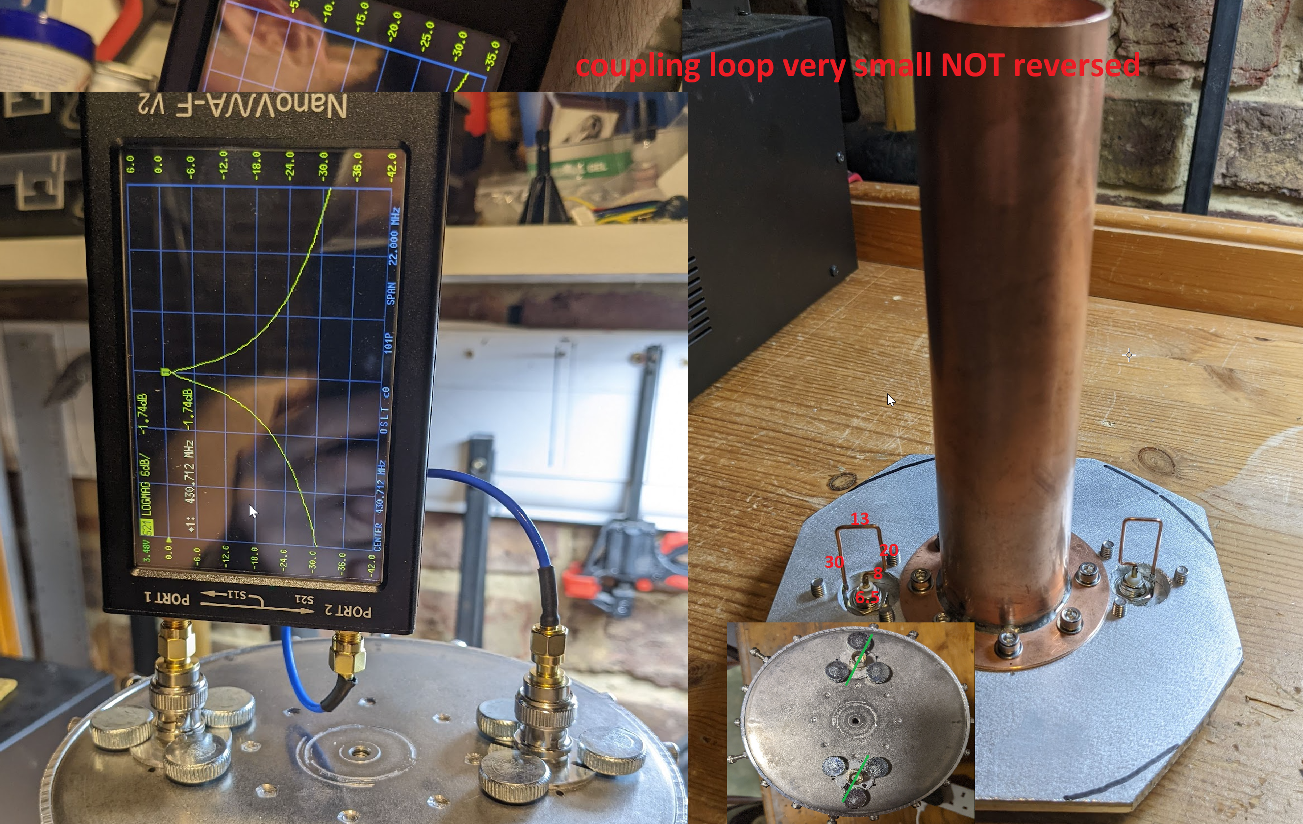
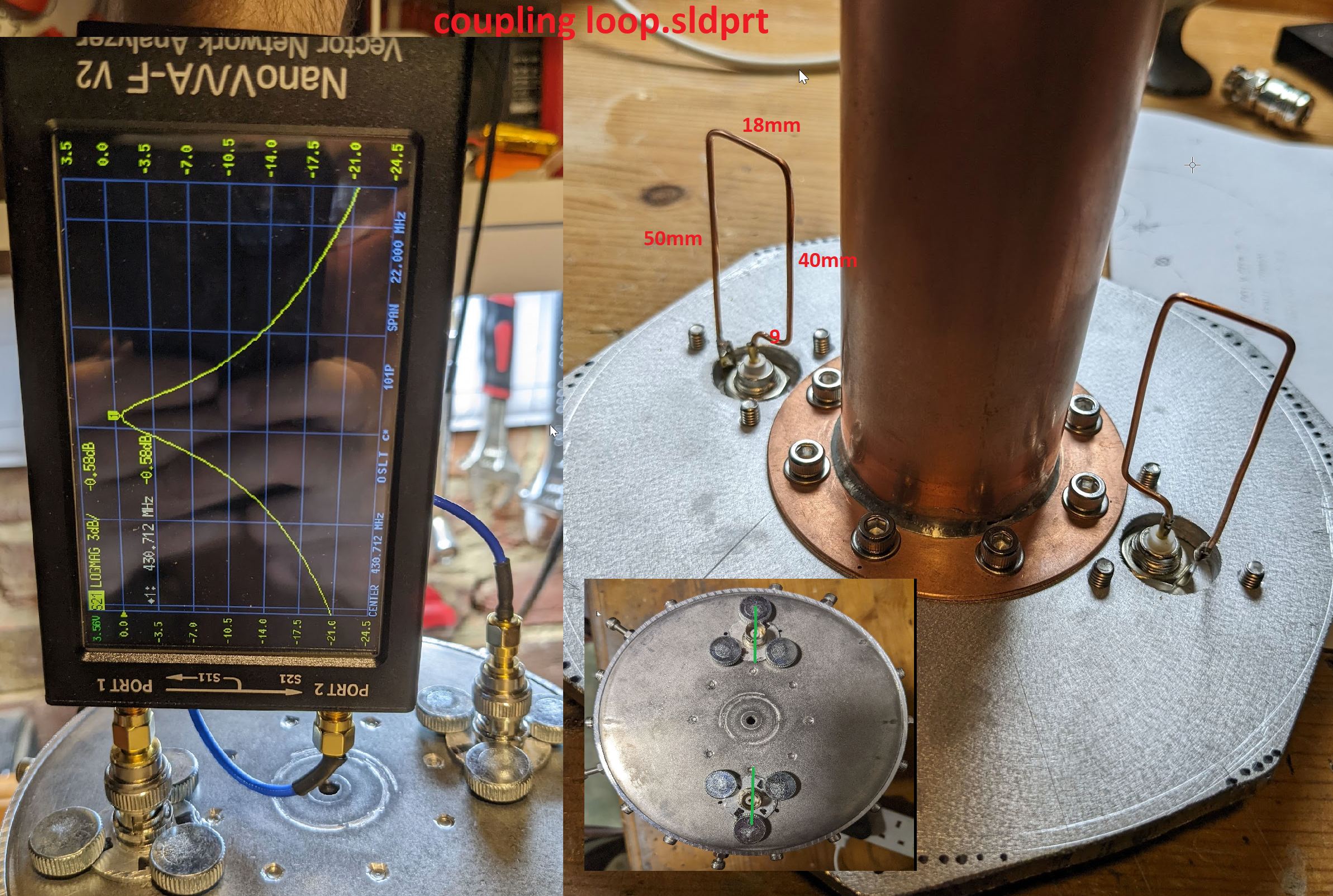
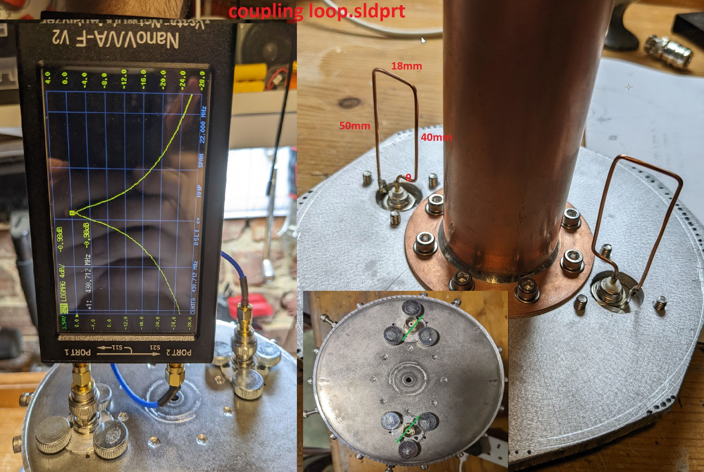
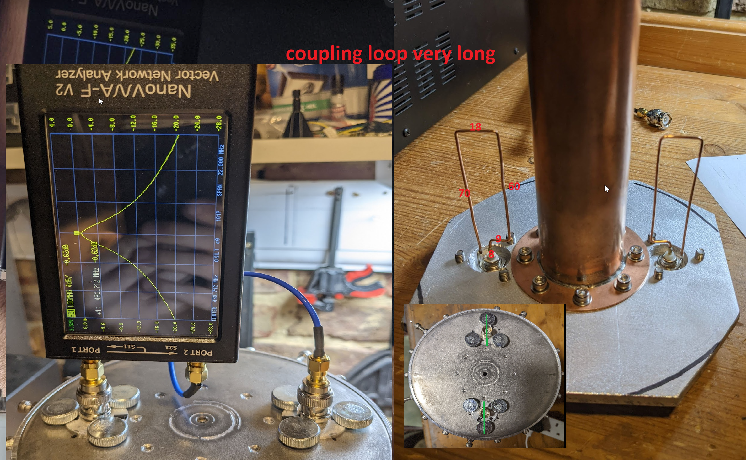
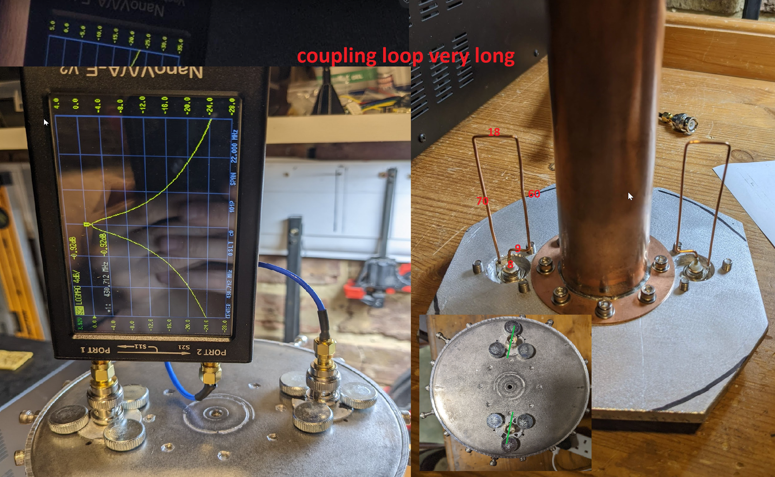
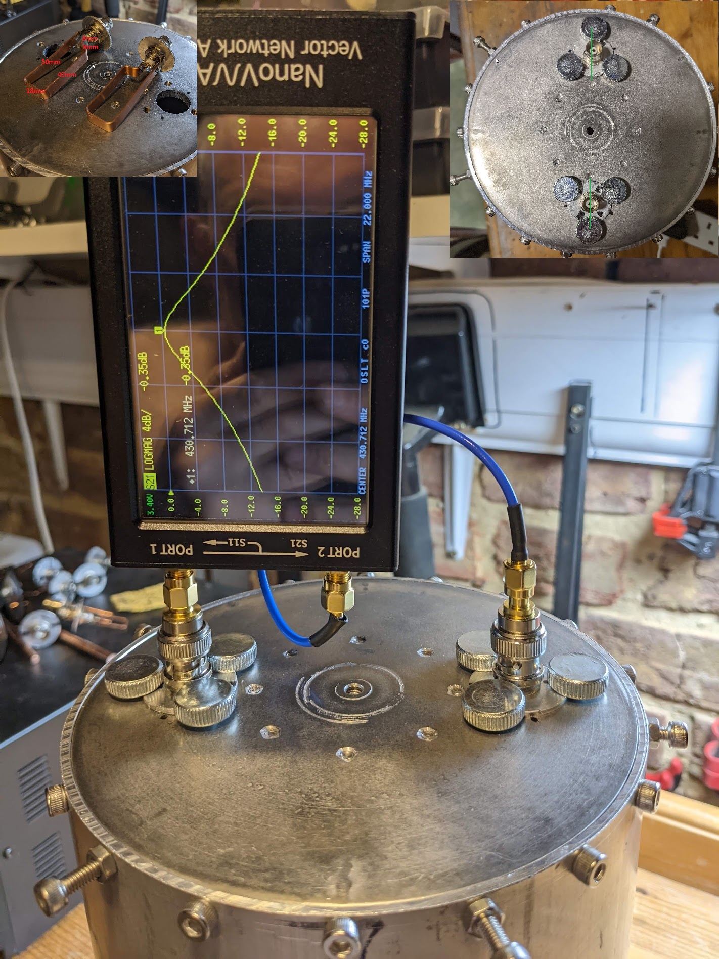
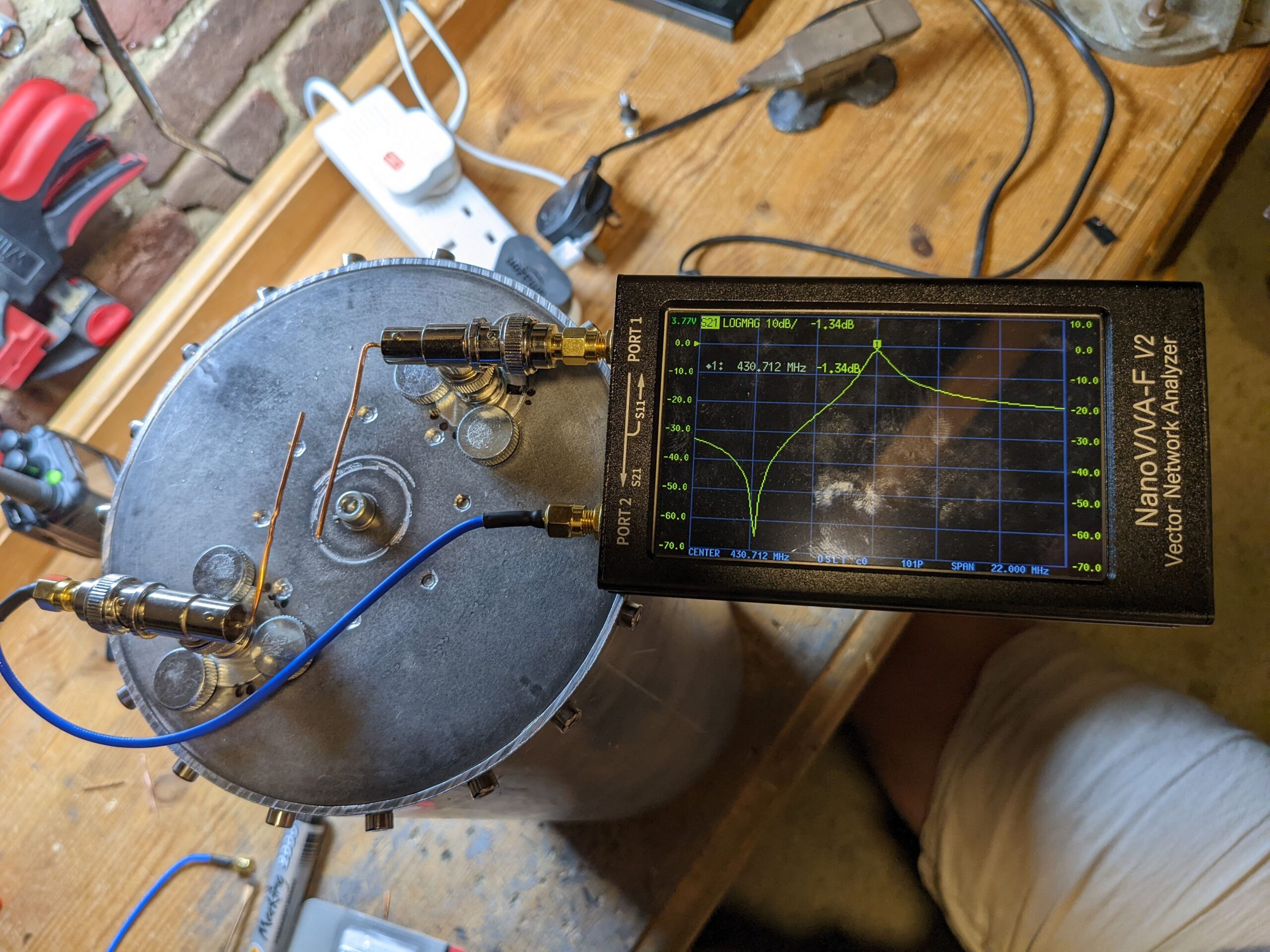
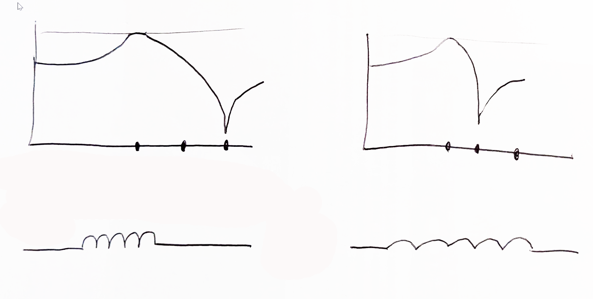
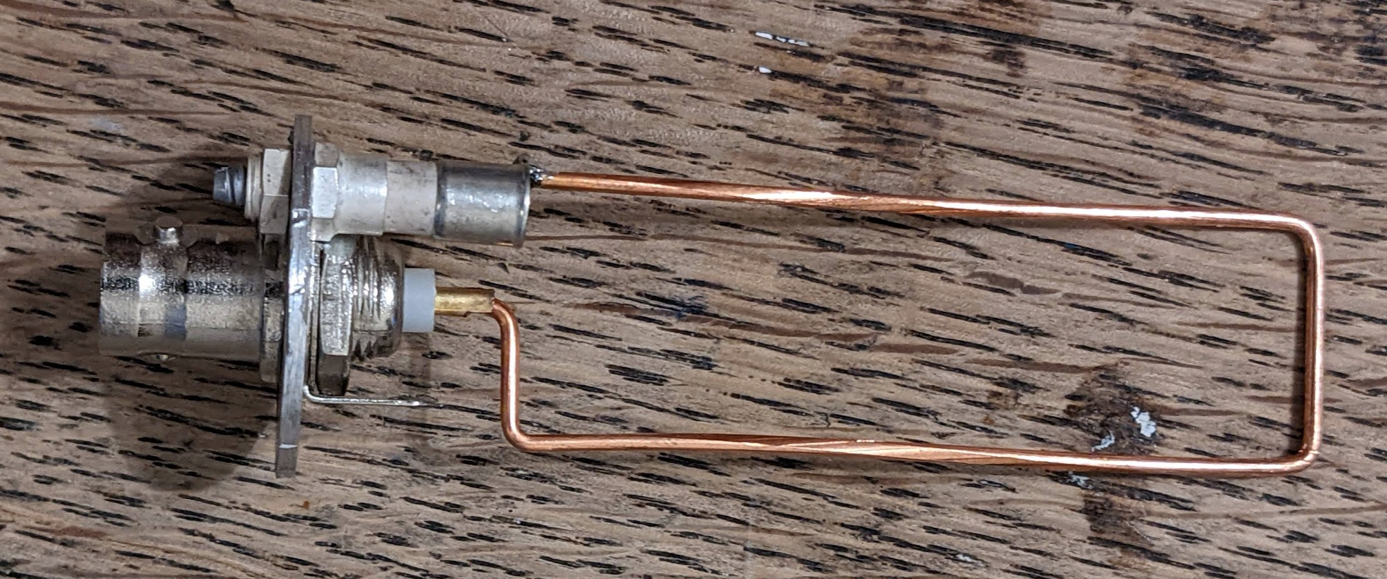
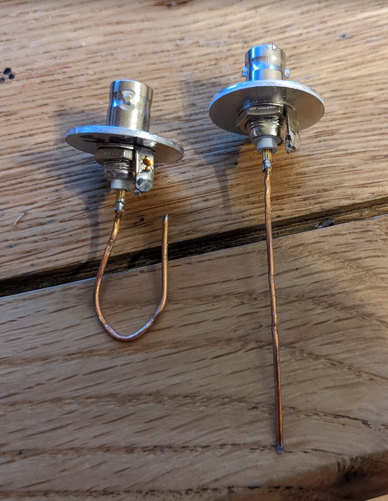
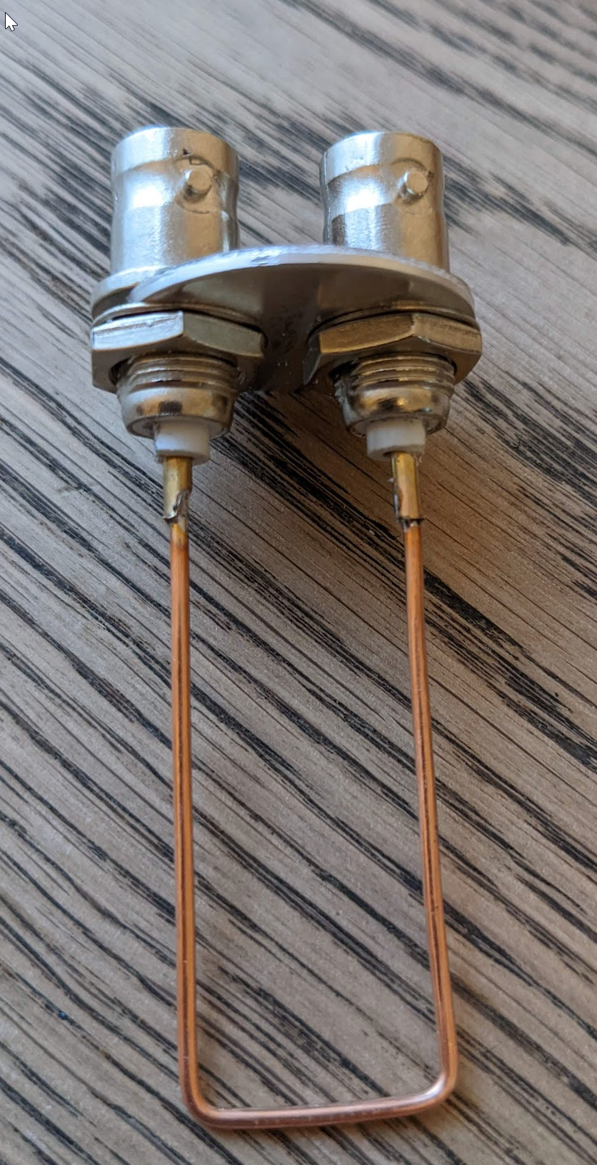
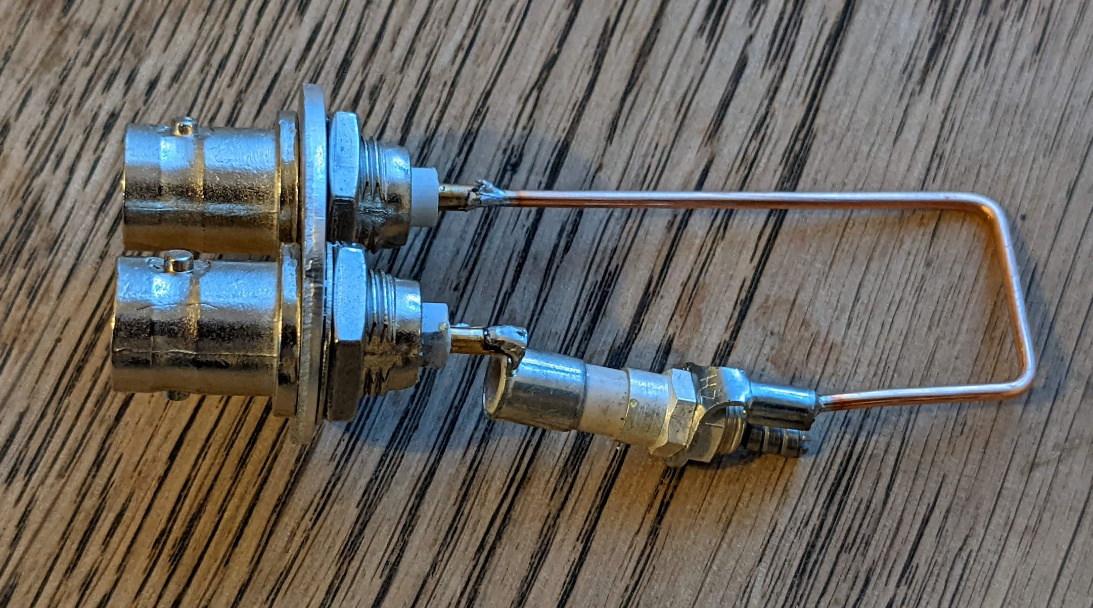
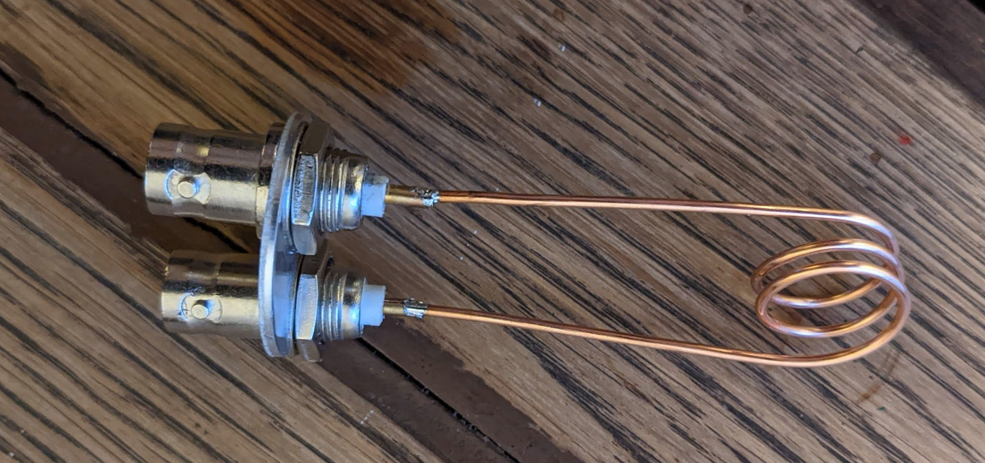
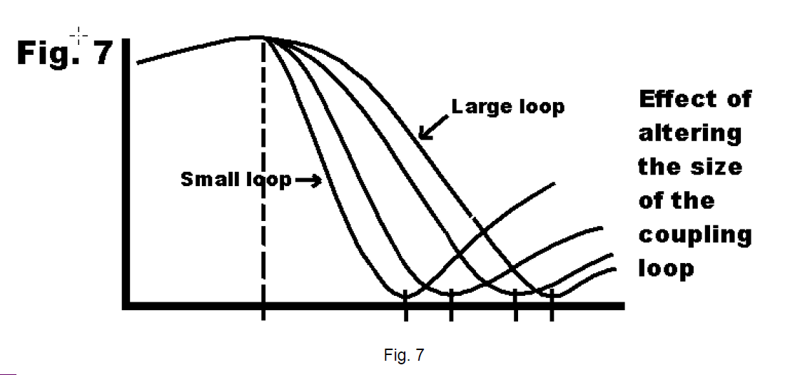
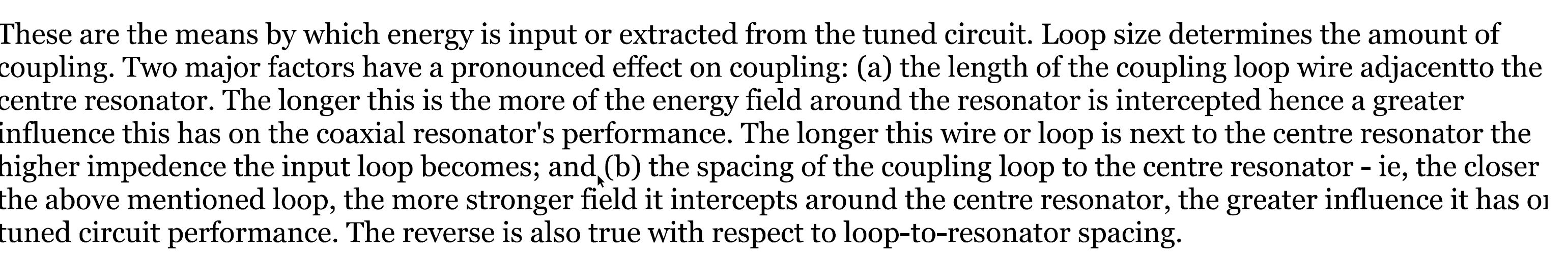
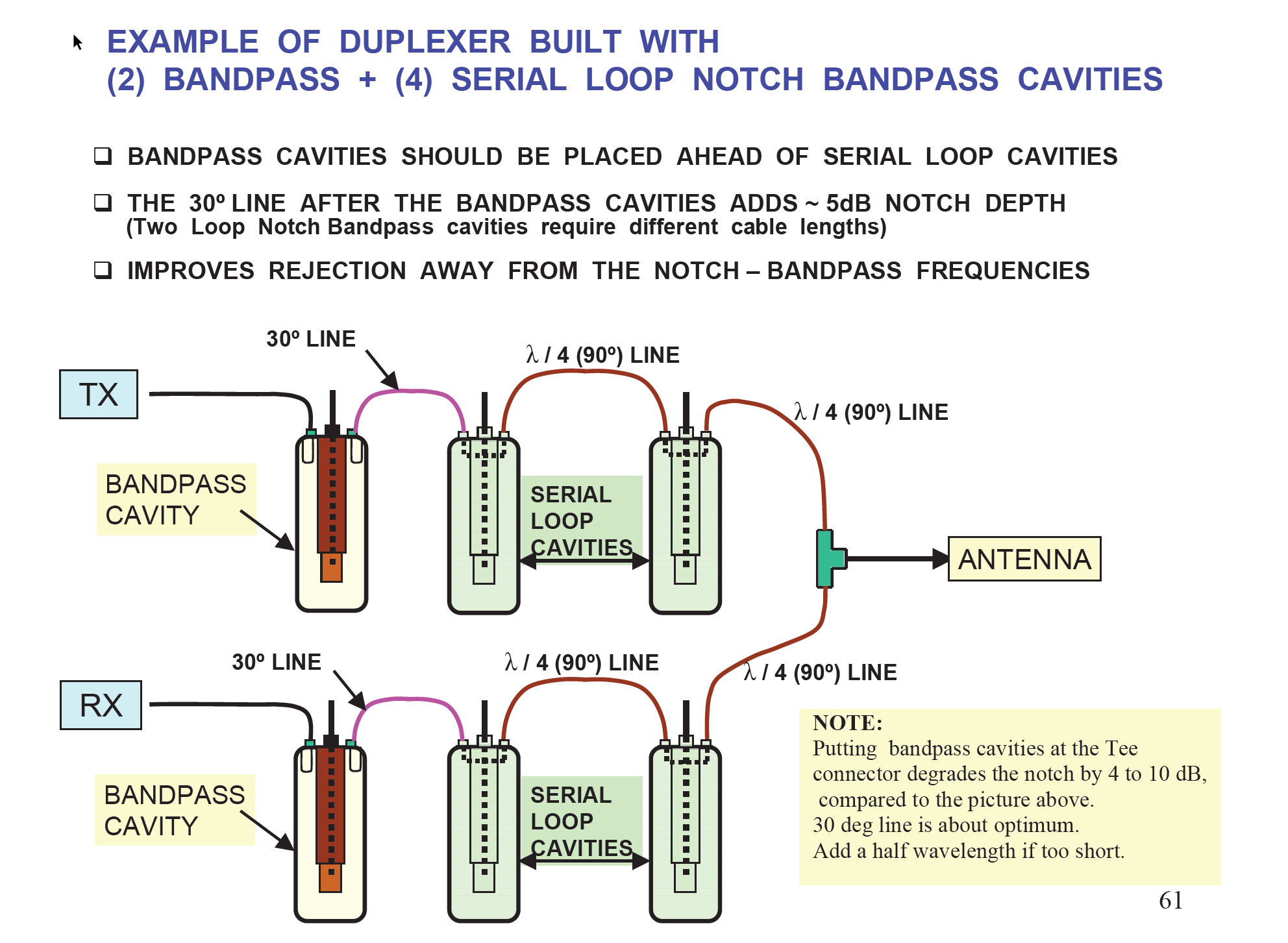
Playing with cavity coupling loops.
The problem was that you can find quite a lot of information about making cavities tubes, centre conductor, how to tune it, what material use, but it was quite difficult to find out how coupling loops are made. I did not know how long to make them, how wide, how close they can be to the centre conductor, if the centre of the BNC connector should go to conductor direction first, or actually away first:
I did many tests and I publish results below. Surprisingly all sizes coupling loops were giving almost the same results, however the “very small” size loops were not responding very well to rotation, leaving results similar regardless the position of the loops. Also rotating them 180 degrees for any size was not changing a lot.
So actually according to one website I found, the length, profile shape, distance from centre conductor is NOT critical at all! How wired! Only critical is the rotation angle.
Finally I decided to use a size I called “standard” however made from a flat copper bar 7 x 1.2mm. The advantage of the flat bar copper over the rounded diam. 1mm copper wire is that in the straight position looses are only 0.35dB, but I could not see any advantage when the coupling loops were rotated. So no need to use flat bar instead of diam. 1mm wire. Also I played with pushing the loops closer or further away from the centre conductor and very surprisingly it did not affect the results too much.
PS. I am aware of making things silver plated, but for cost reason and 1 off job I gave this up. Also silver plating improves everything just a little bit.

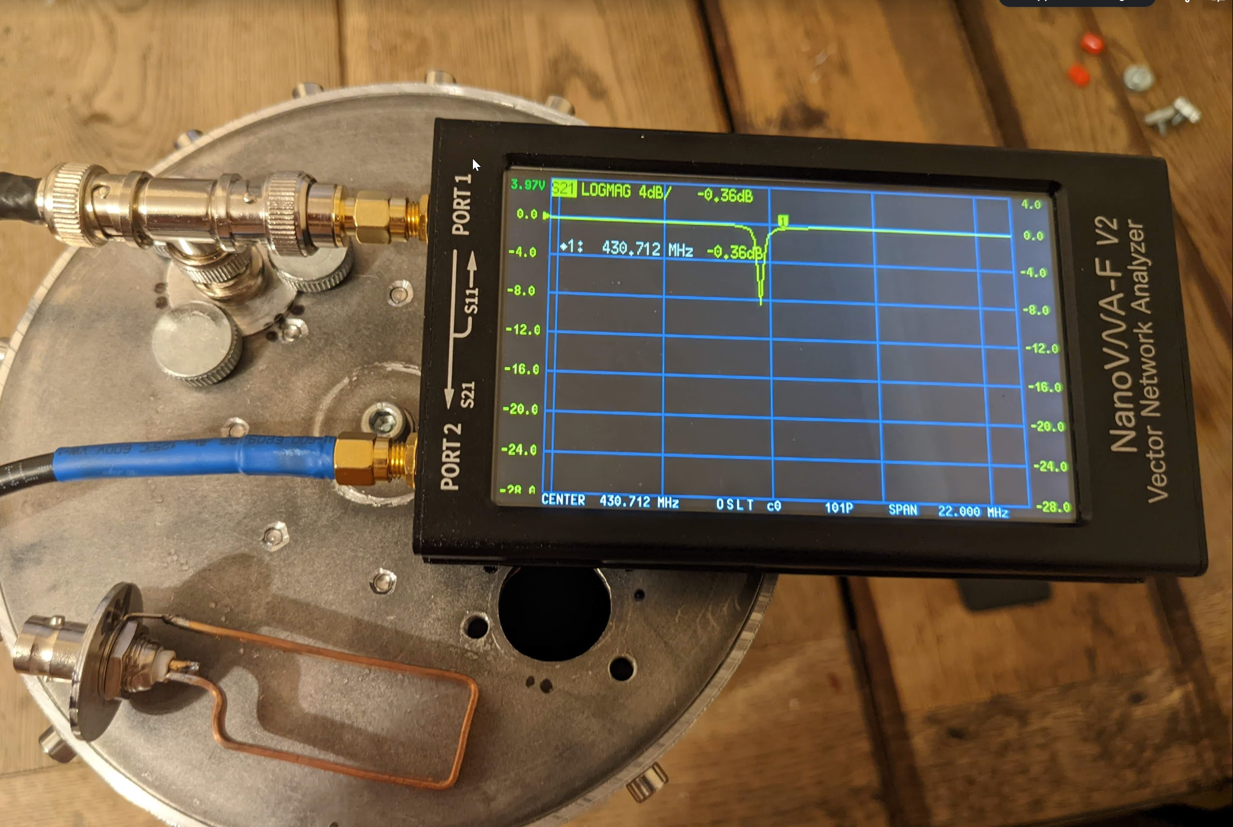
Some experiments with a single cavity:
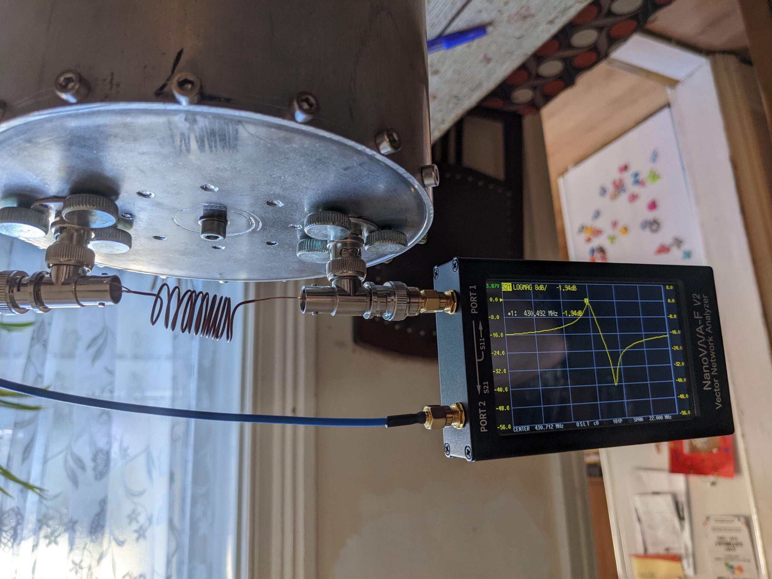
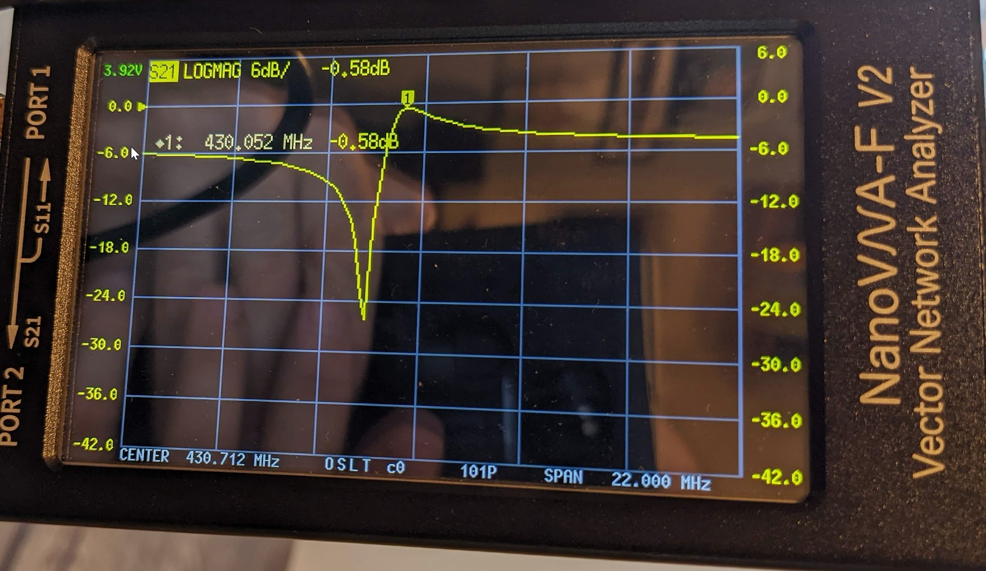
So I replaced the wires which worked as capacitors with a proper air trimmer capacitor and… it failed!! The cavity notch went to the other side!!!!!! Why??? I am guessing the problem was the air trimmer had to big inductance and started working as inductor. The set up capacity was not changing too much!! – see pic below:
Now the tests with real inductors – it failed quite badly. Why? Because regardless what I was doing with the coils (inductors), regardless how many turns I made on whatever diameter, the notch was ALWAYS close to the centre frequency as I was UNABLE to move it further away. I even tried to put a straight wire between Tee’s to minimise inductance but it did not help. The notch was stubborn and kept itself al the time roughly 2…3 MHz away from the centre frequency. See few pictures below:
I found what was wrong 🙂 Skip three picture below showing the problem.
A PROPER SOLUTION:
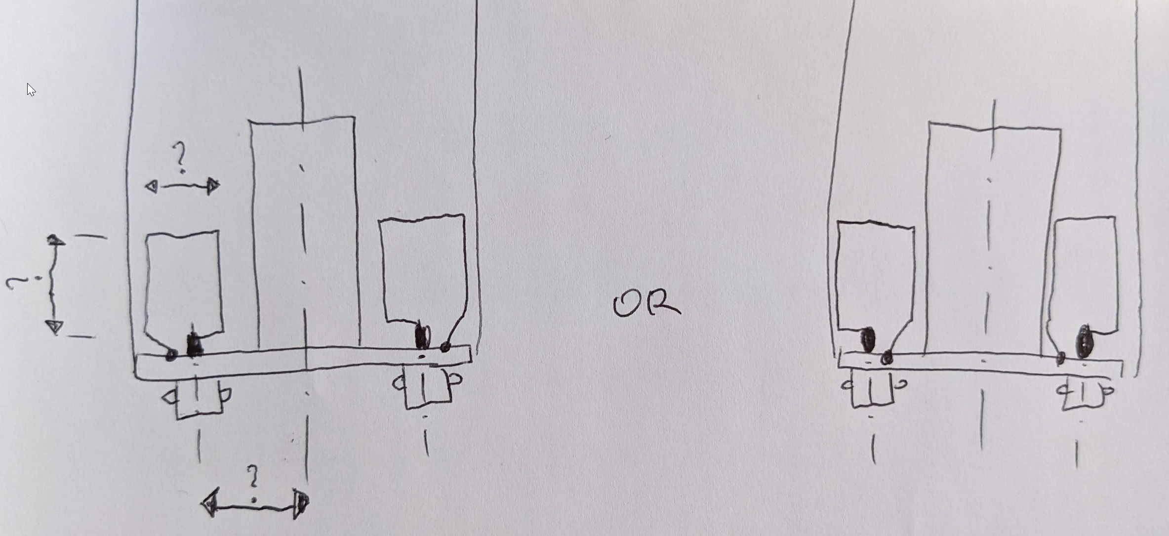
I badly assumed that I can keep a small angle on coupling loops (roughly 30 deg) – the same as I was getting the best result for the band pass filter! This time the solution is to keep it perfectly perpendicular to the centre conductor. PS. The frequency needs tuning with the bottom screw – but the most important thing is that I found a solution to get a correct 9Mhz split for the RX part of the duplexer. I show some sample coils and their results. Stretching coil brings the notch closer to the centre frequency, shrinking the coil bringing the notch further from the centre frequency.
Some coil sizes – see sample pictures below:
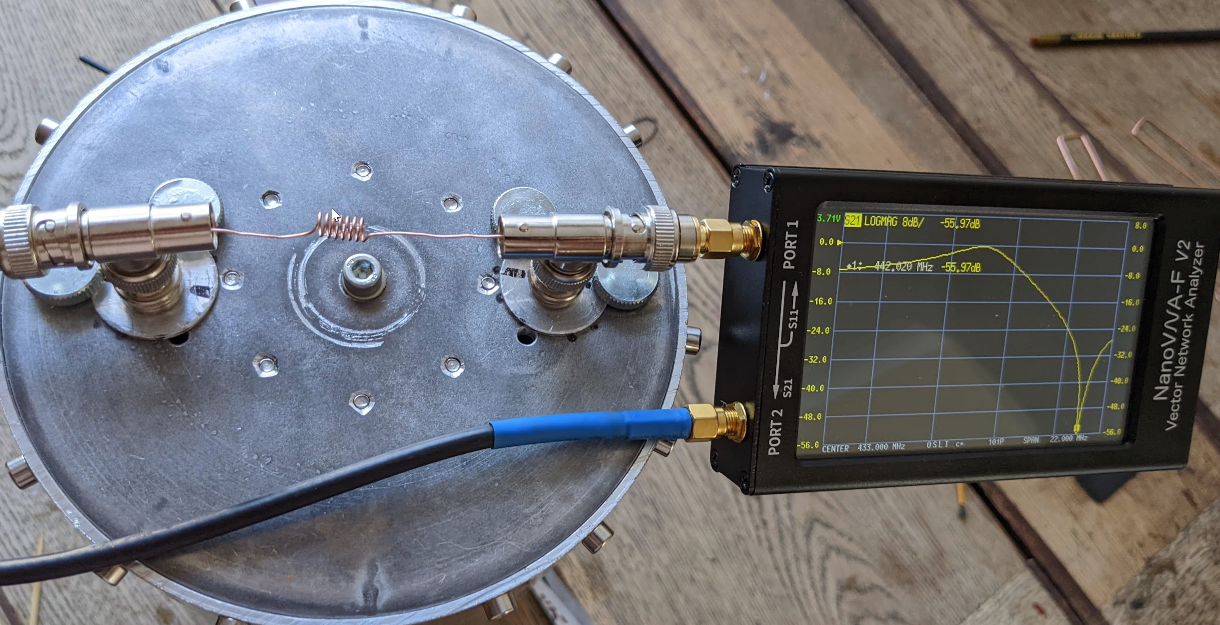
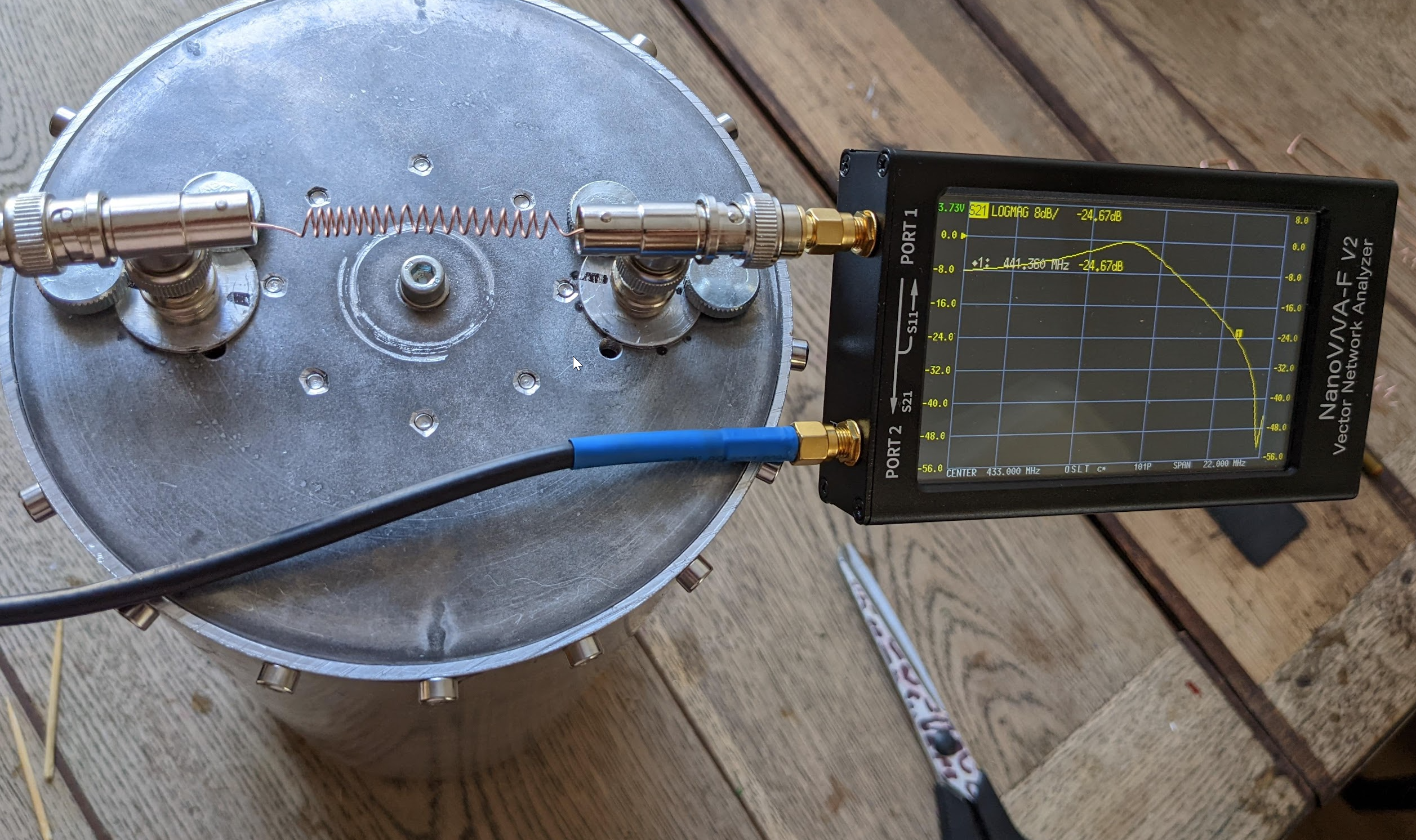
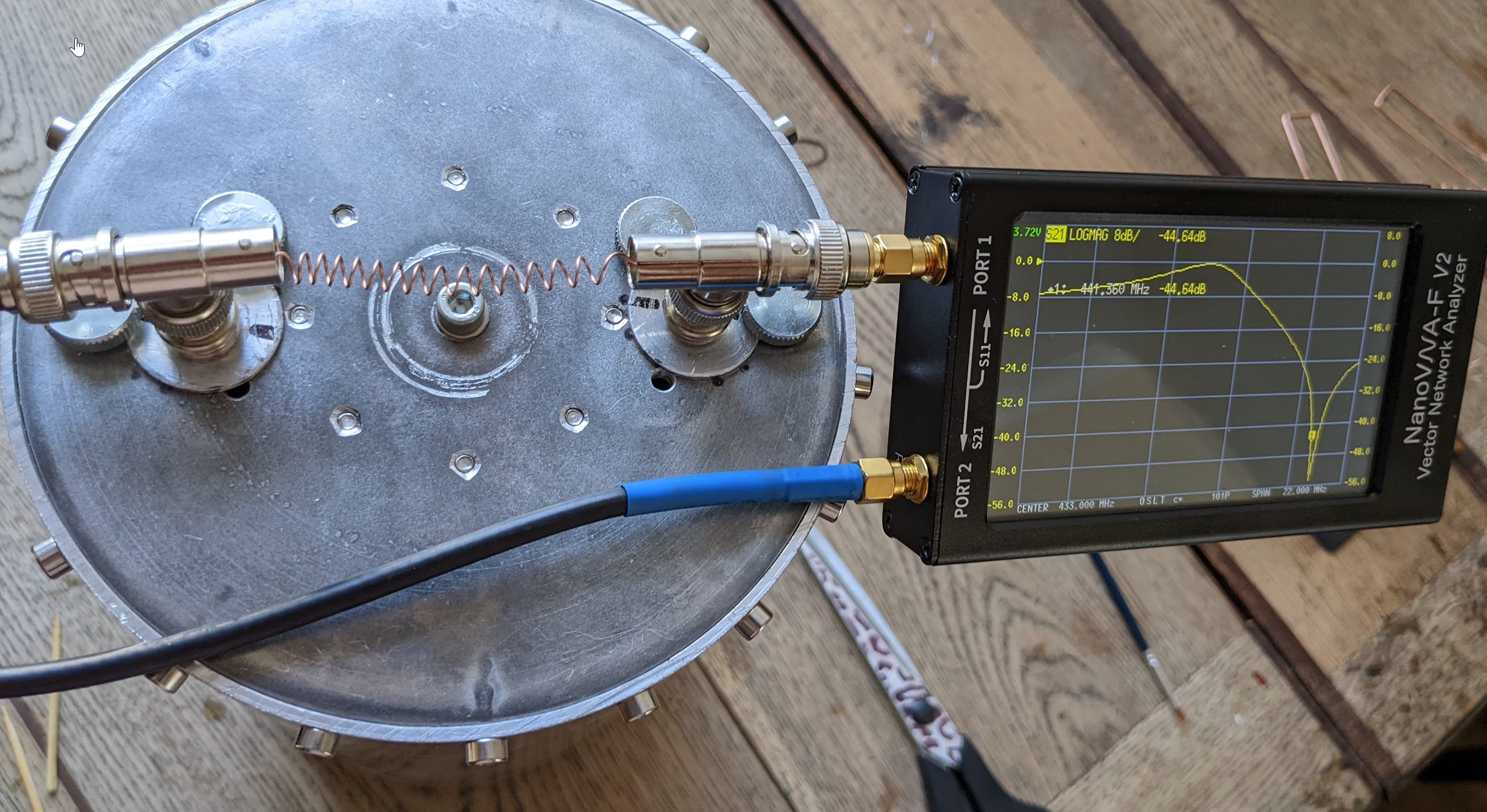
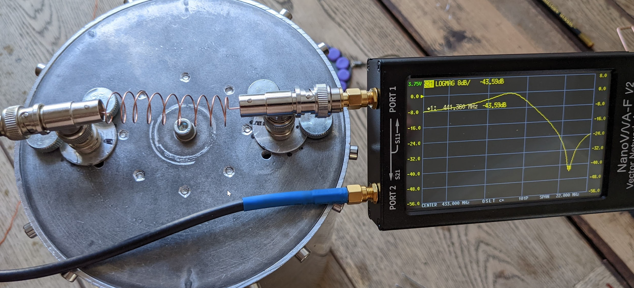
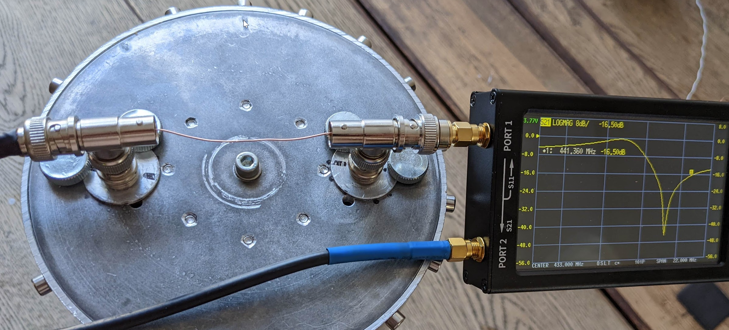
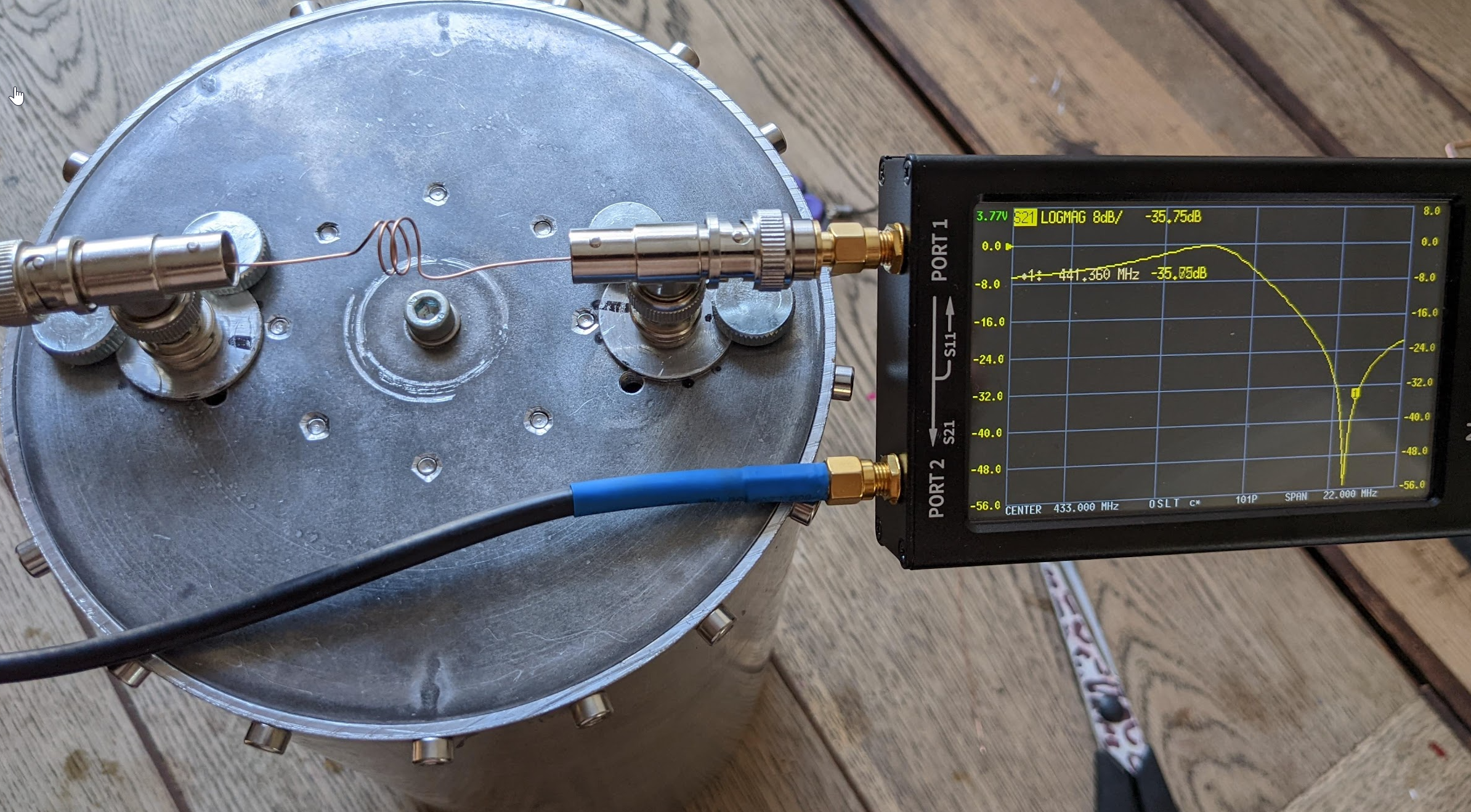
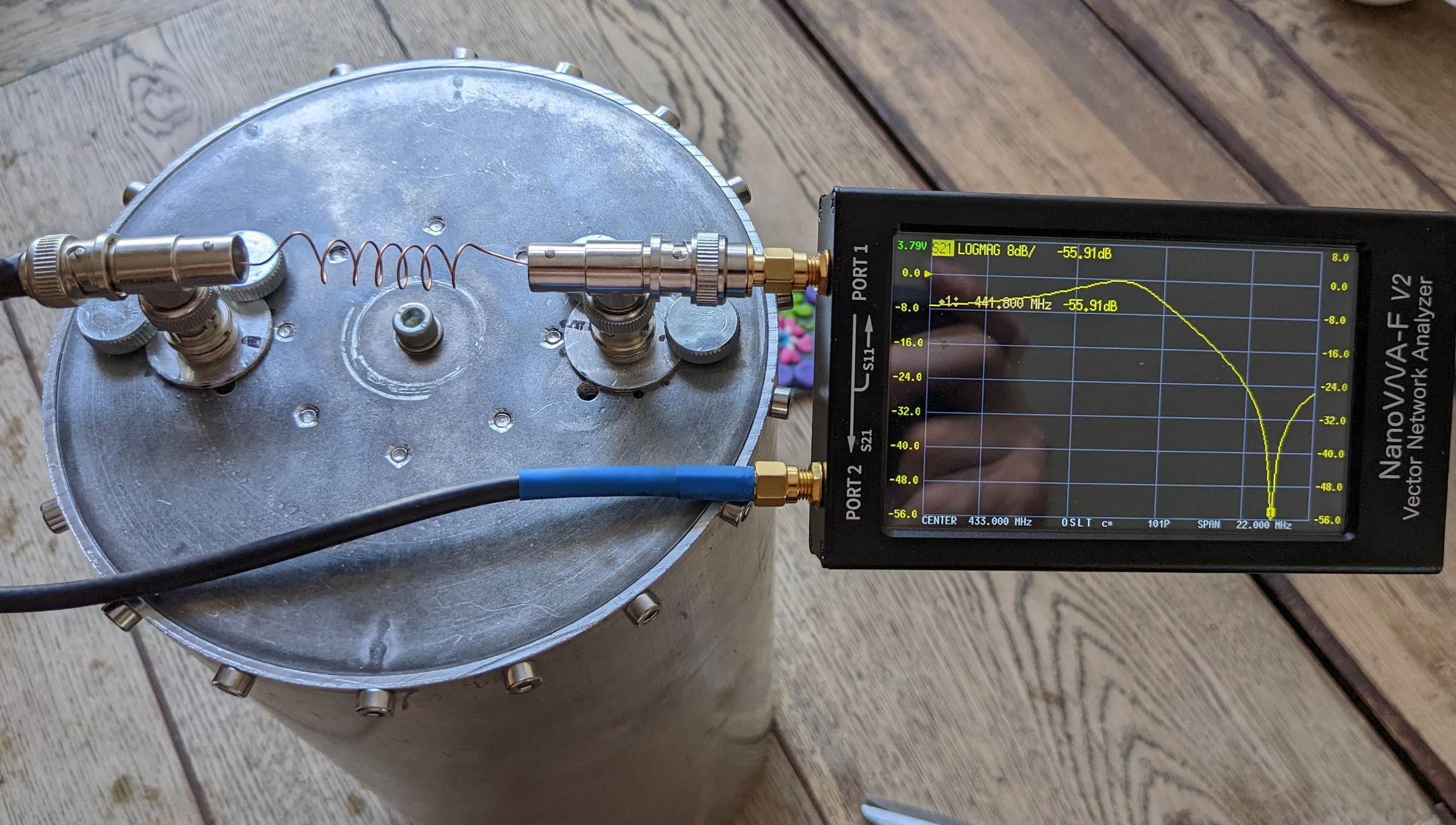
And another few pictures showing the coil dependency to the notch frequency, this time it was a test with a 4” aluminium cavity:
For 160mm conductor (RX with coil) I found that 160mm makes resonance at 434.0MHz
Smaller diameter – closer the notch to the pass (desired) frequency, bigger diameter – notch will be further from a pass frequency. For a final tuning – tighter the coils turns are – the notch goes further away from the desired frequency, looser the turns are – notch is closer to the desired frequency.
Some other tests I have done with coupling loops:
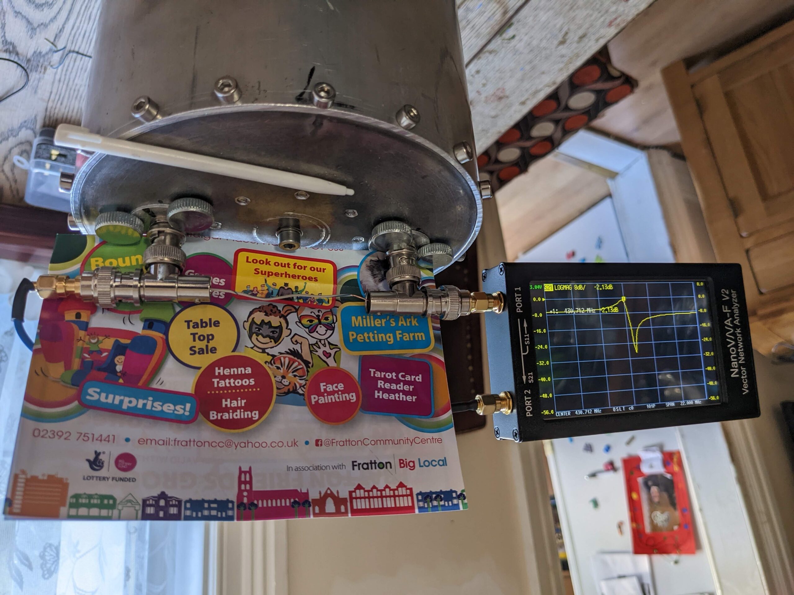
Another test I did was a single band reject loop. So I just simply removed one couplign loop and I stayed with the other one. The result – very disappointing – is below:
So time for the other test. I added a nice 0.8pF…10pF Johanson trimmer:
With the maximum capacity of 10pF the chart is shown below:
However the result become much better when I reduced the capacity to the minimum – actually I made a opened loop – as there was no capacity in the trimmer – result was much better (28dB) but the frequency moved to 433MHz! Also 9Mhz to the left the loos is almost 0dB! However 28dB attenuation is not very impressive.
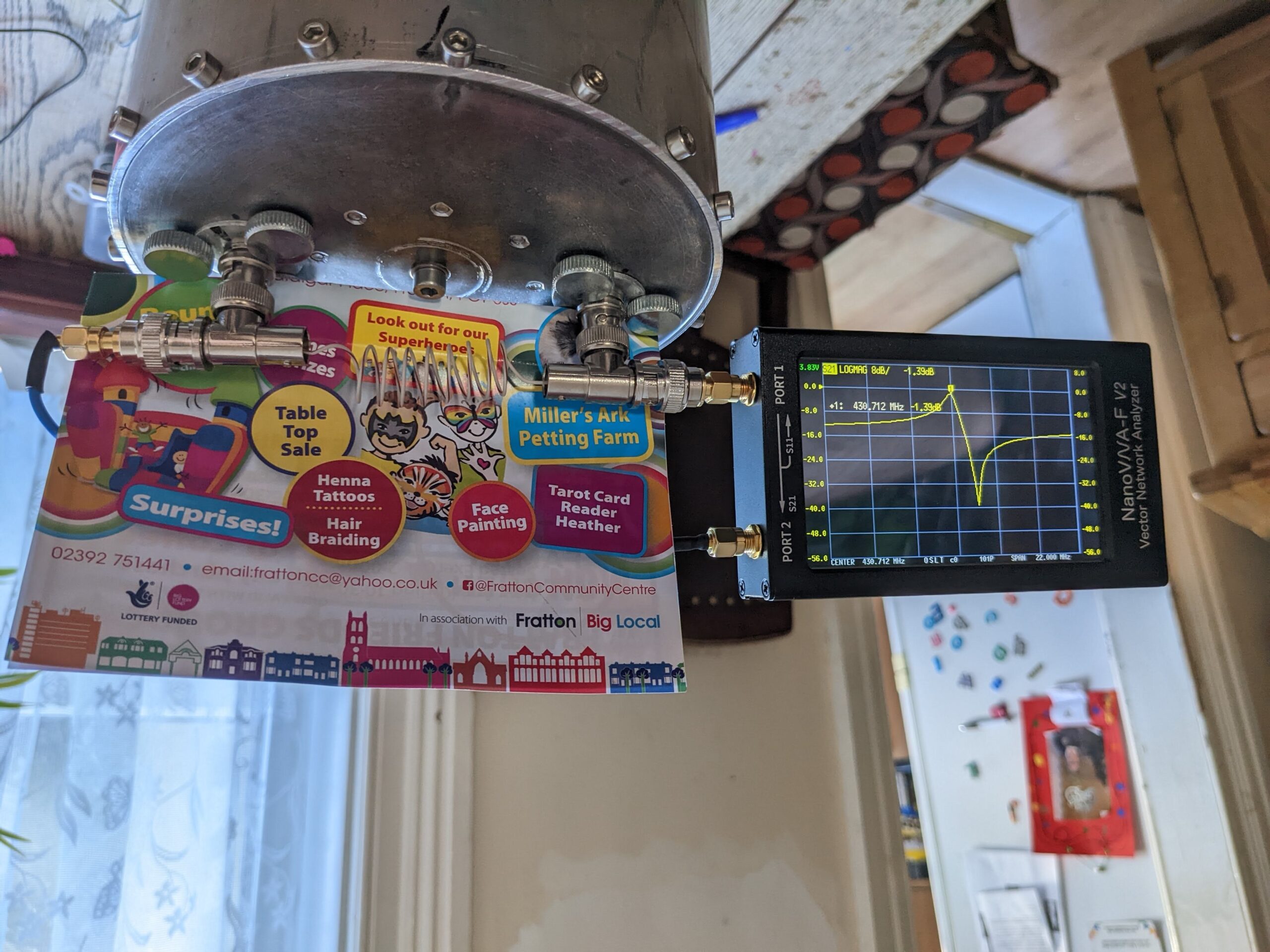
I have also made some silly couplings as shown on the pictures below, but the chart was just flat – so they did not work at all.
and the result for the above
And this time once turn less:
As you can see on all charts above, I struggle to get a correct shift between the chart bump and the notch for RX. I always get around 3MHz only where I need 9MHz! Just recently I found the chat below, which probably will help me to get required 9MHz! Tests to follow very soon! Sorted by keeping coupling loops NOT on the angle (roughly 30deg), like for the band pass filter, but perfectly rectangle to the centre resonator.
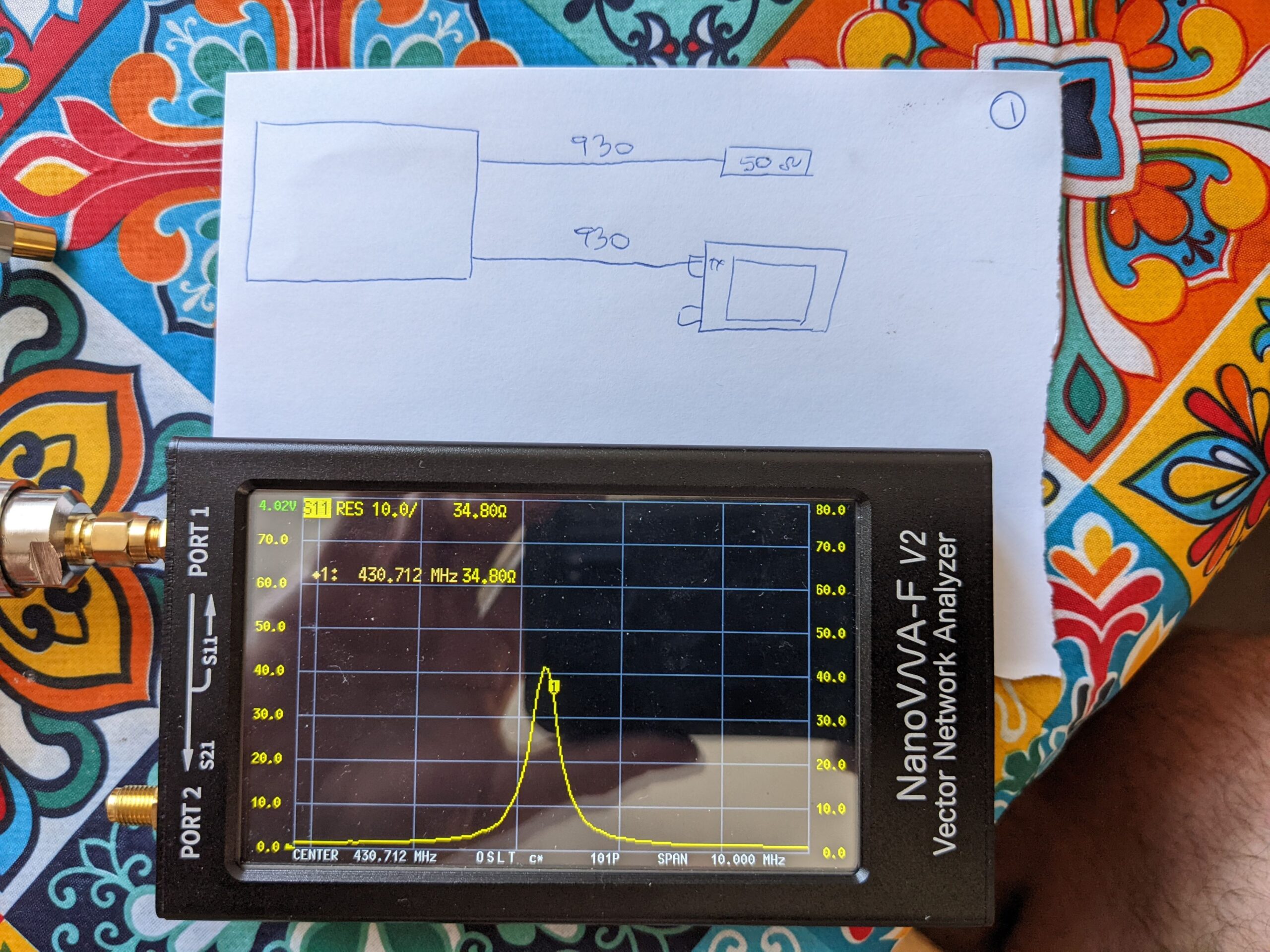
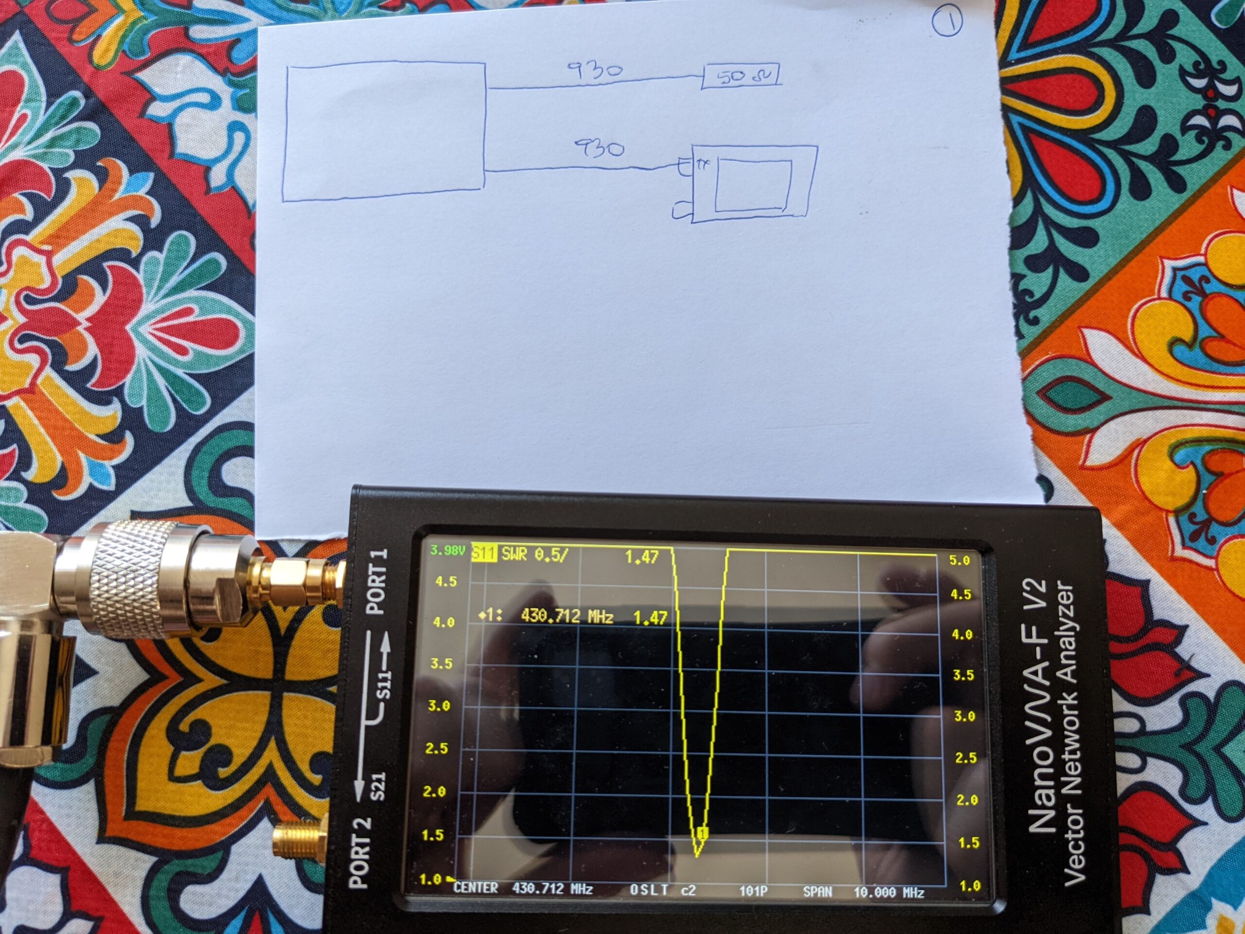
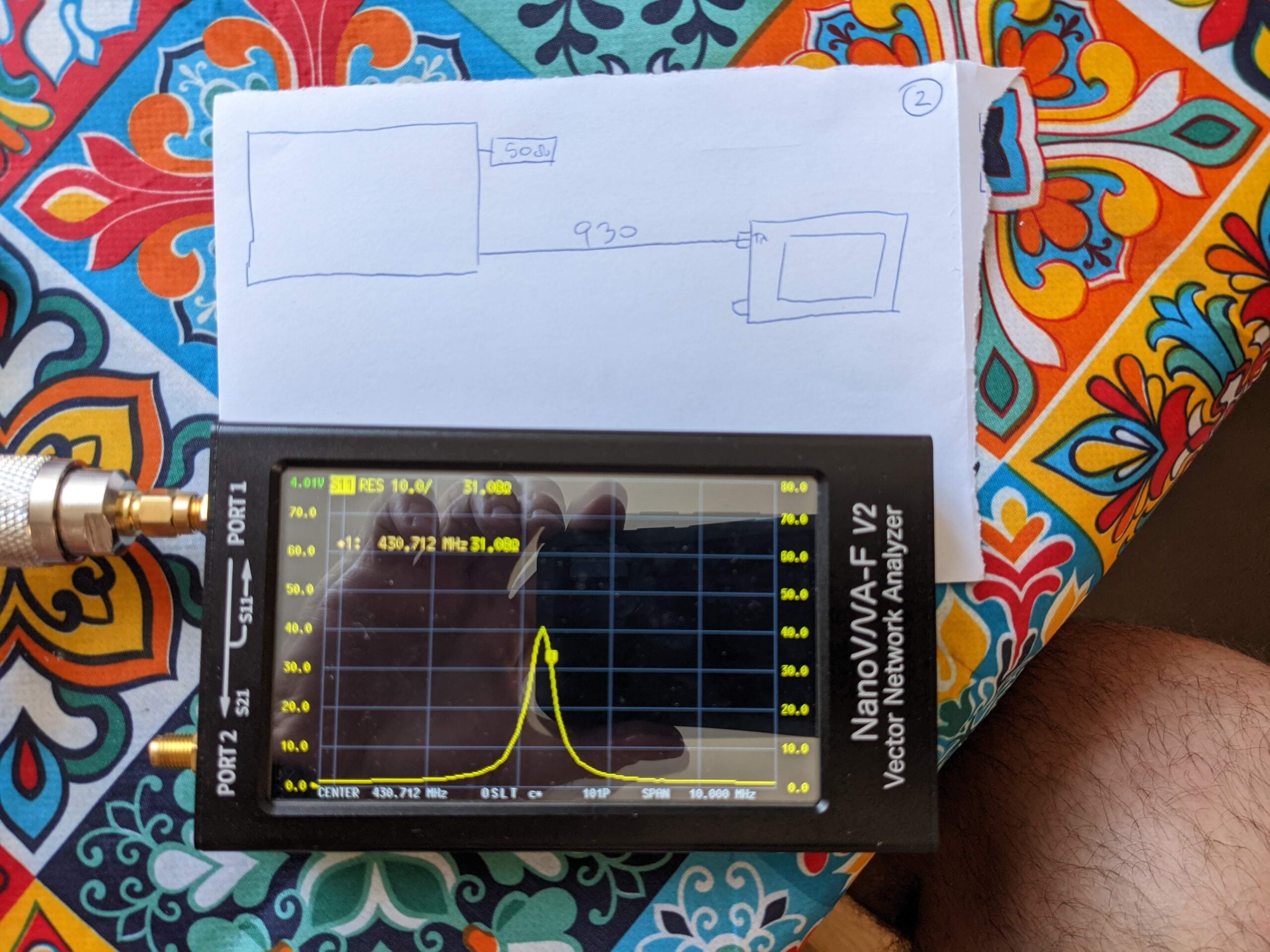
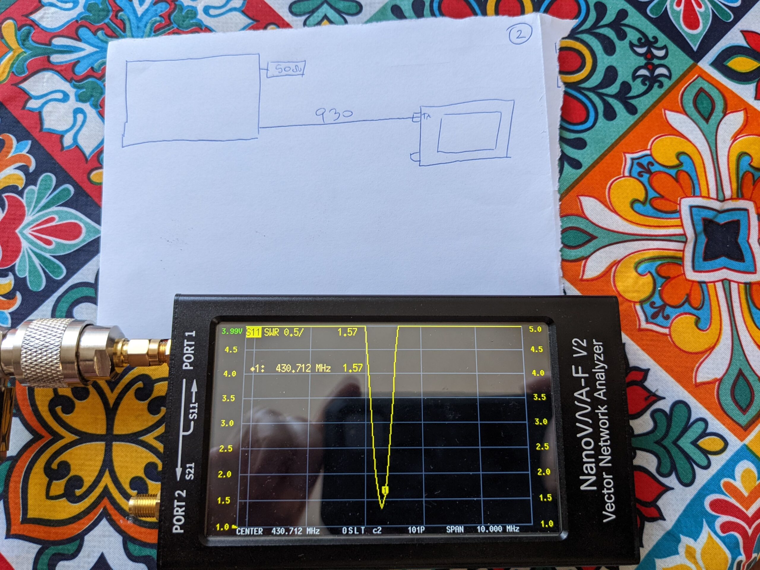
Playing with cable length for cavity – to achieve 50 Ohms.
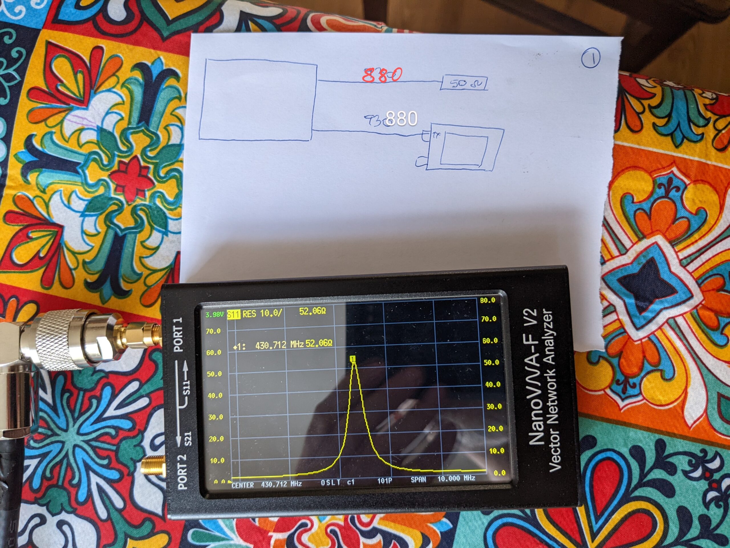
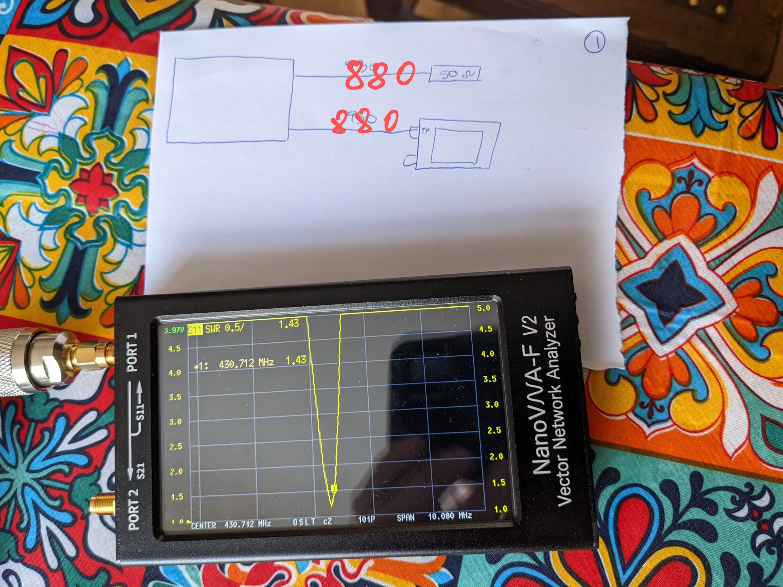
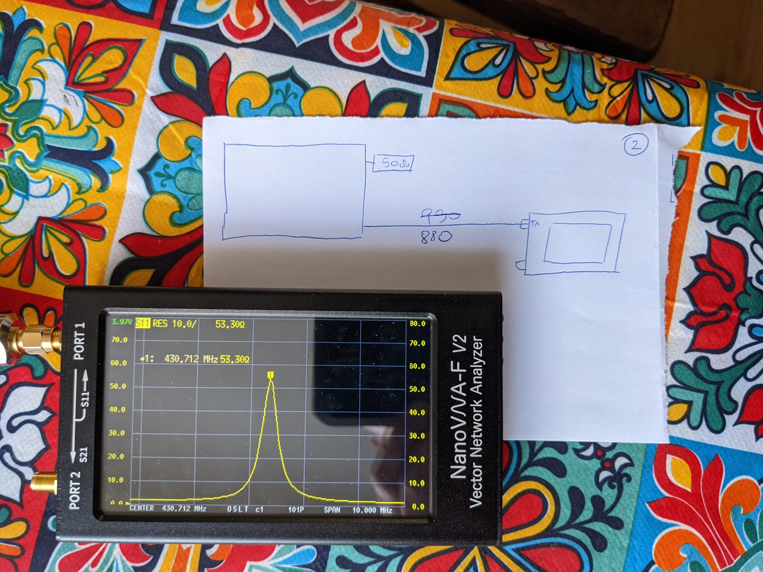
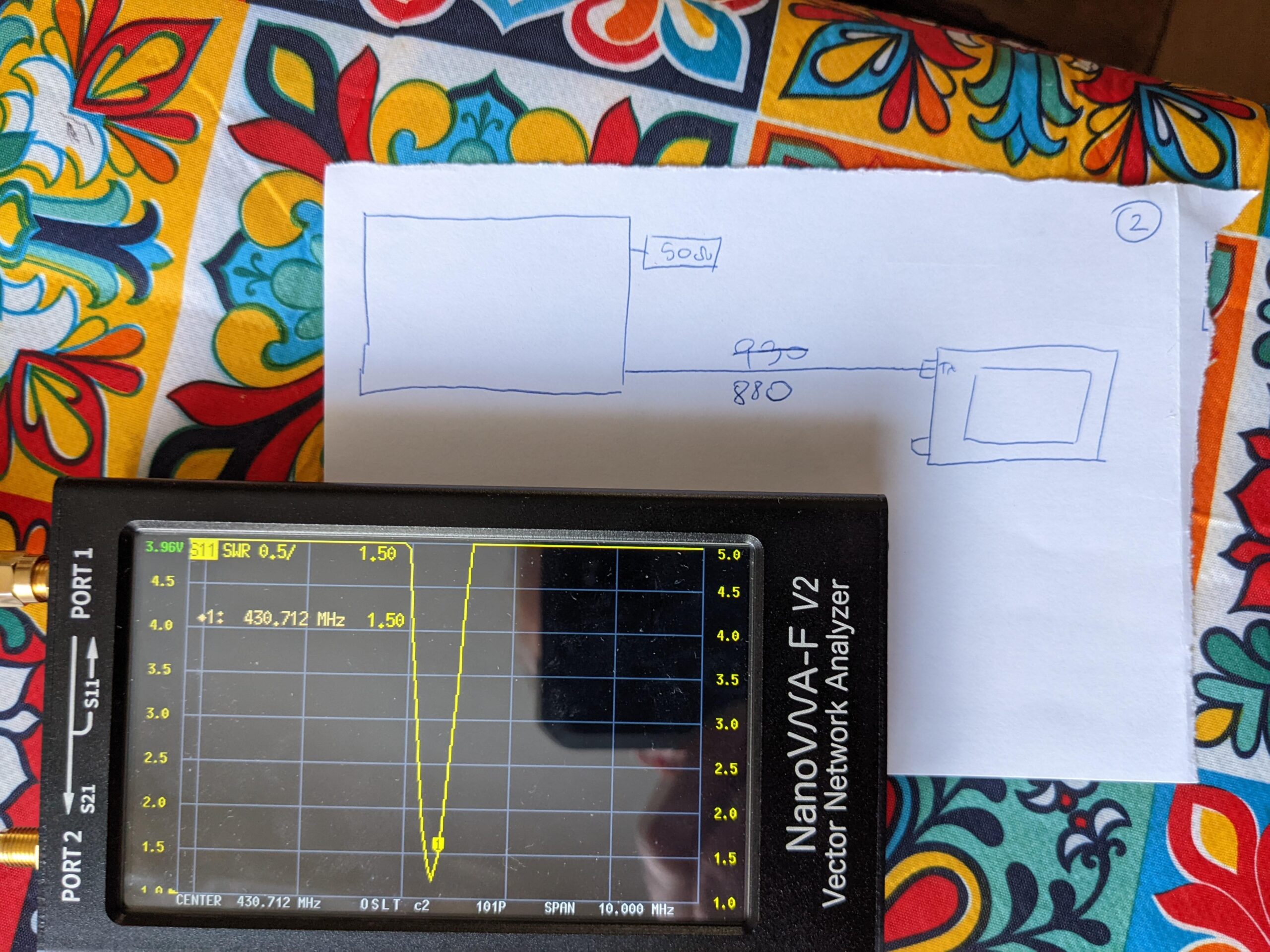
As I mentioned before for now my repeater is using the mobile duplexer, however Chinese hands did not care too much about making that right and the duplexer makes the receiver in my repeater desensed. To improve the situation I decided to make a single band pass cavity. The cavity is placed on the repeaters enclosure so I needed quite long cables. Regardless the cables are long or short, the length should be set up to transform impedance to 50 ohms. My cavity impedance is about 75 ohms. So when I set up the cavity, I randomly used cables 930mm long. The rule says that you need to use quarter wave length cables (minus velocity factor) and also minus the length of the coupling loops. Practically it is impossible to calculate the length of the cables. Then you can multiply the length by as many half wave lengths as you like:
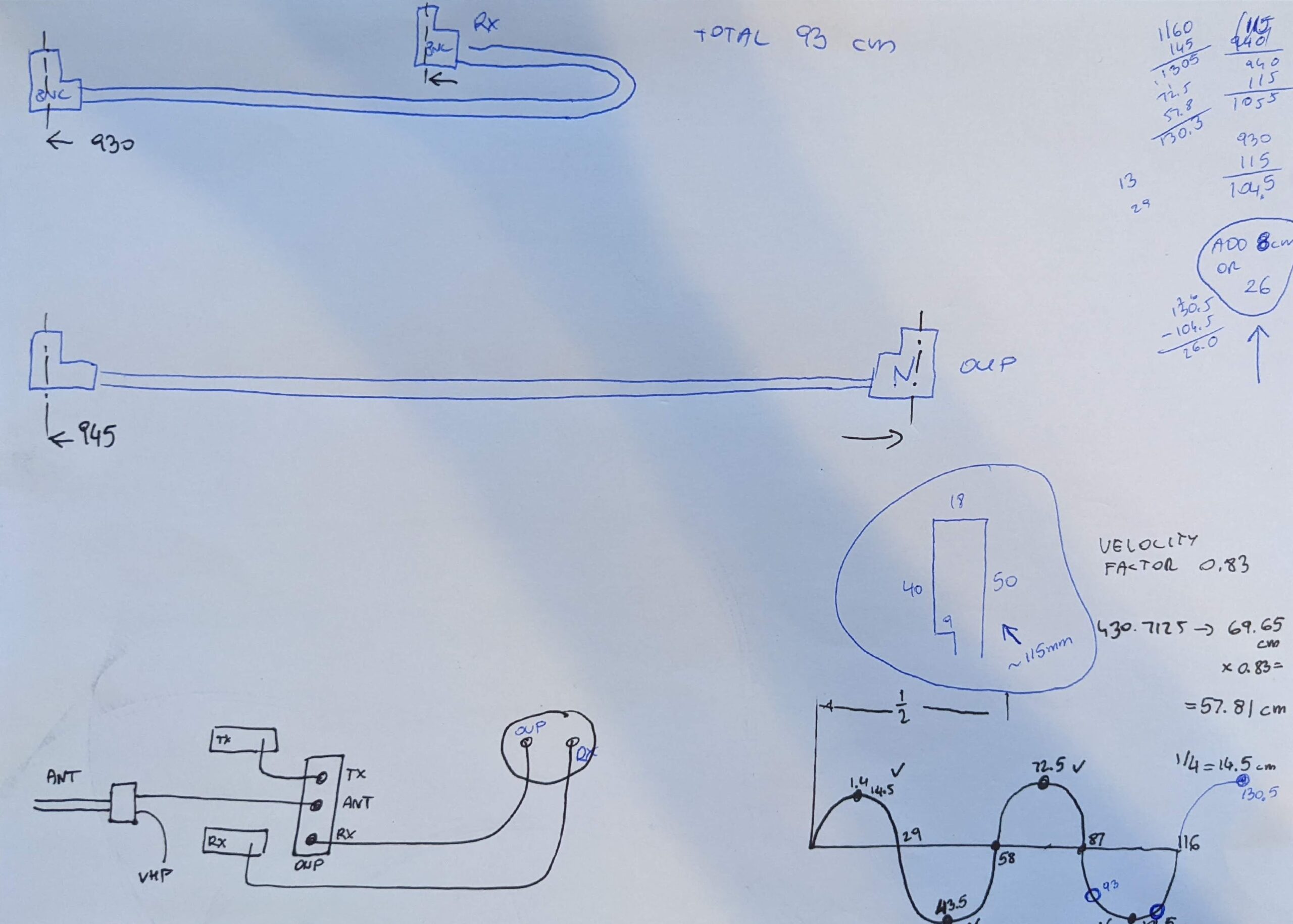
Bottom right corner – shows that you can have a cable as long as you wish, however you need to trim it in exactly right place.
I found later that my cables at length 930mm provide 70 ohms impedance – not disaster but needs to be 50 ohms.
Hi, your work on cavities are interested but I didn’t see anything about cold, heat and wet climate influence on metallic structure of cavity filter. Performance of filtering could be affected.
73
Laurent F1NFY
Very nice article, lots of work gone into it, thank you very much !
Did you know that the optimum RF cavity impedance (highest Q) is around 77 Ohm ?
With your current AL100 dimensions, your cavities coaxial impedance is around 100 Ohm, so maybe try to either increase your resonant rod diameter from 22mm to 28mm, or reduce the cavities internal diameter from ~100mm down to 80mm. Either will give a coaxial impedance of round 77 Ohm (optimum Q ~ best selectivity).
Thank you very much. I am not professional, I just tried to share my knowledge. I don’t understand – all my drawings show 28mm inductor…
I am grateful for all your detailed documentation on these processes, including the strikeout portions.
I’d love to be able to create a couple of high pass cavities for simplex use on VHF frequencies.
#1. For a local Winlink frequency.
There is an ideal location for a Winlink station at a county backup radio location. However, even though Winlink does NOT require duplexers, a good tight high pass cavity would greatly reduce the de-sensing that occurs due to all the other radios at that location.
#2. For APRS radios operated in the same vehicle as regular VHF.
A local radio professional did this to help isolate his APRS from his everyday VHF radio usage. He said it works really well. But he has access to supplies of real VHF cavities that I do not.