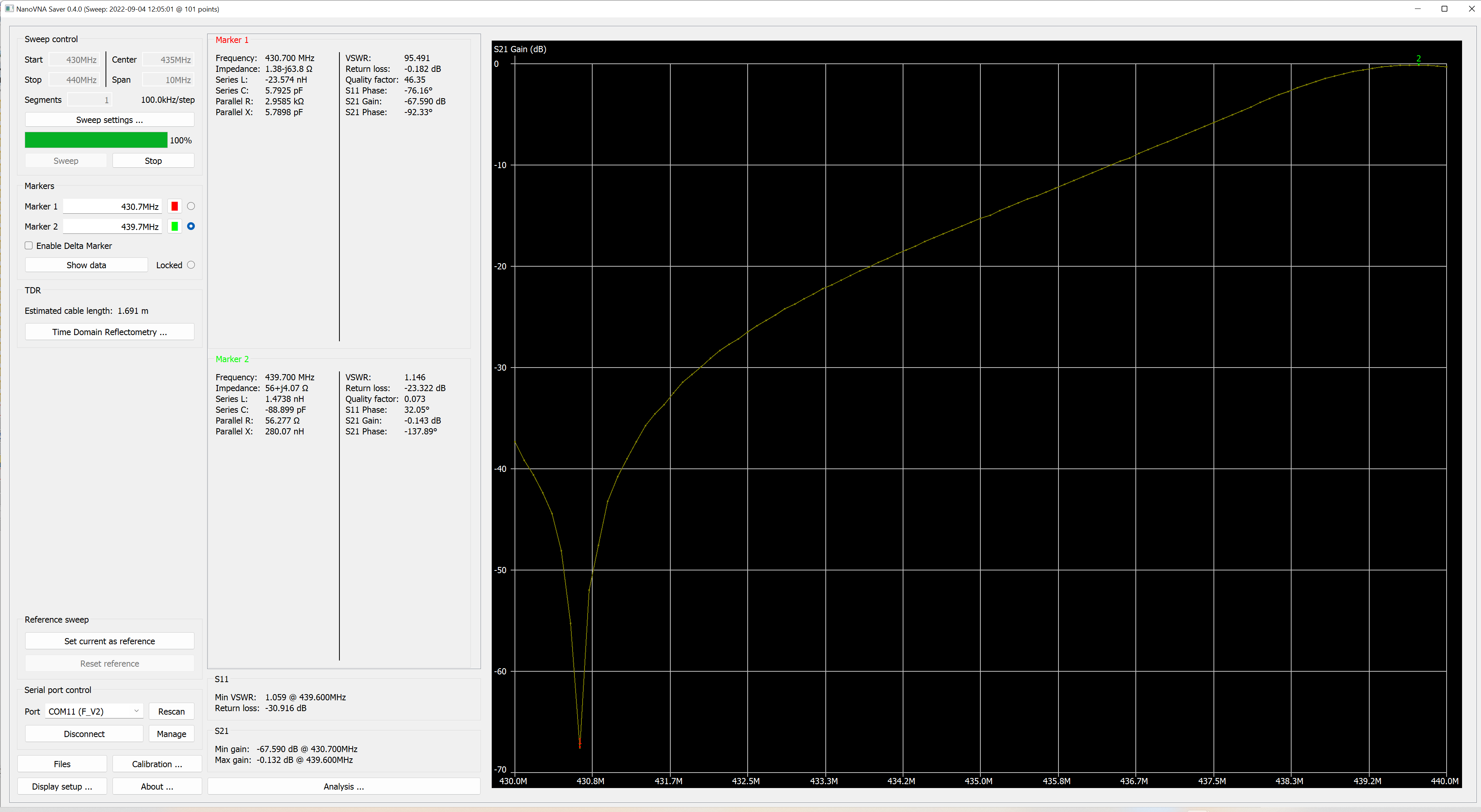
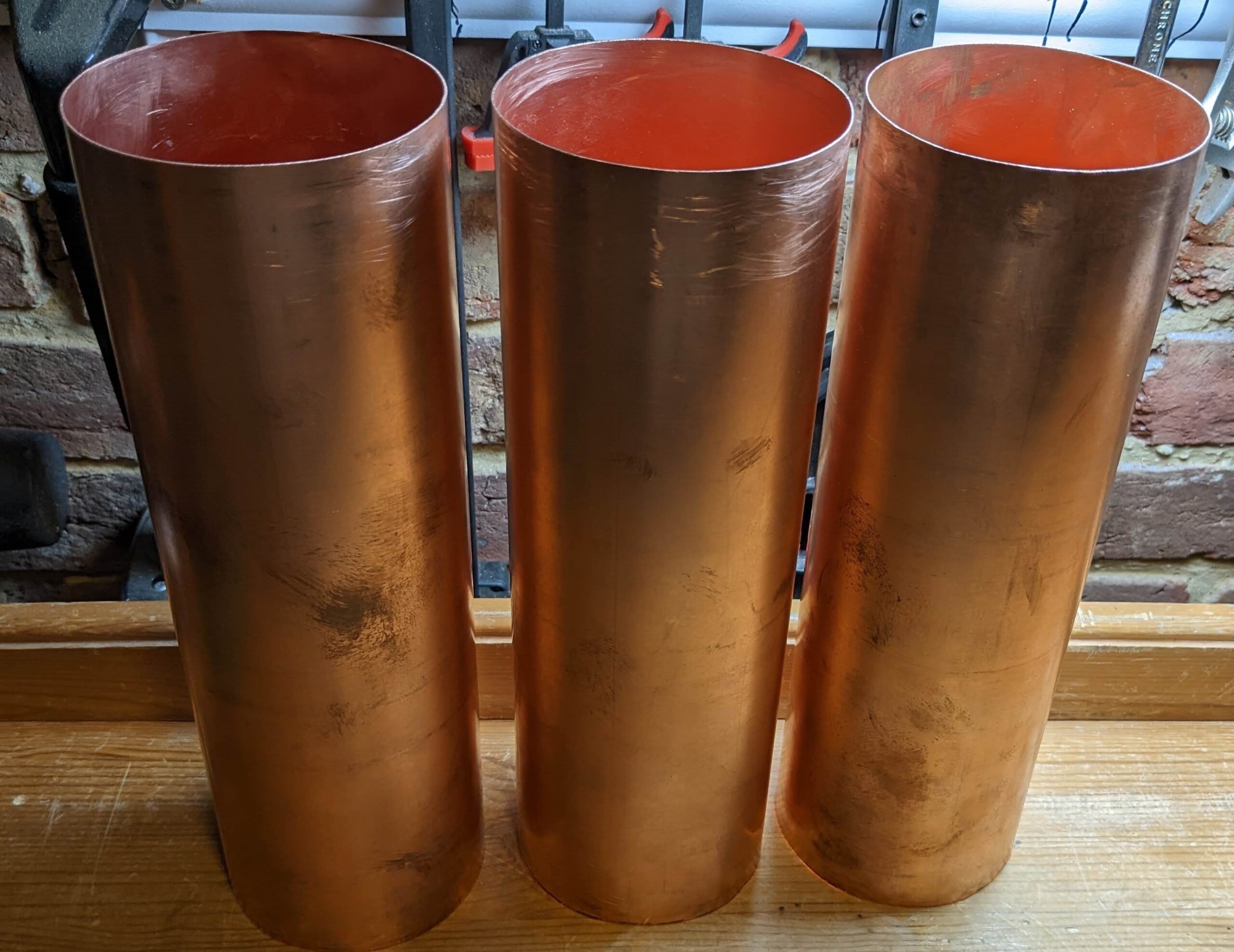
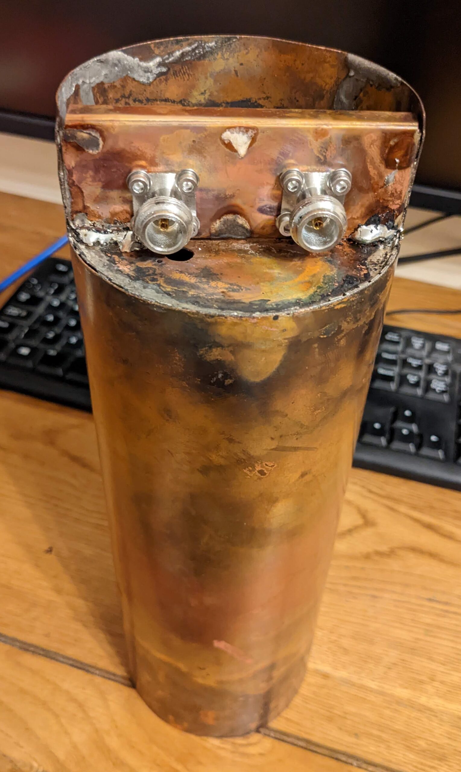
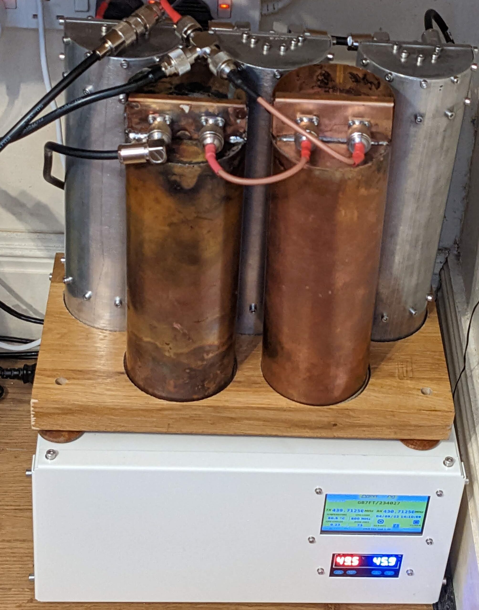
This fully copper duplexer cavity job was based on the project called [AL100] – all details HERE. The only one different was that Project [AL100] was based on the aluminium tubes. Few pictures below show test fully copper duplexer cavities, which were created for two reasons – to see if the assembly process is quicker and/or easier and also to see if the performance is better. I have created only two cavities which are currently working inside of my GB7FT repeater, their performance is great – almost 70dB (9MHz split) notch attenuation per cavity!!!
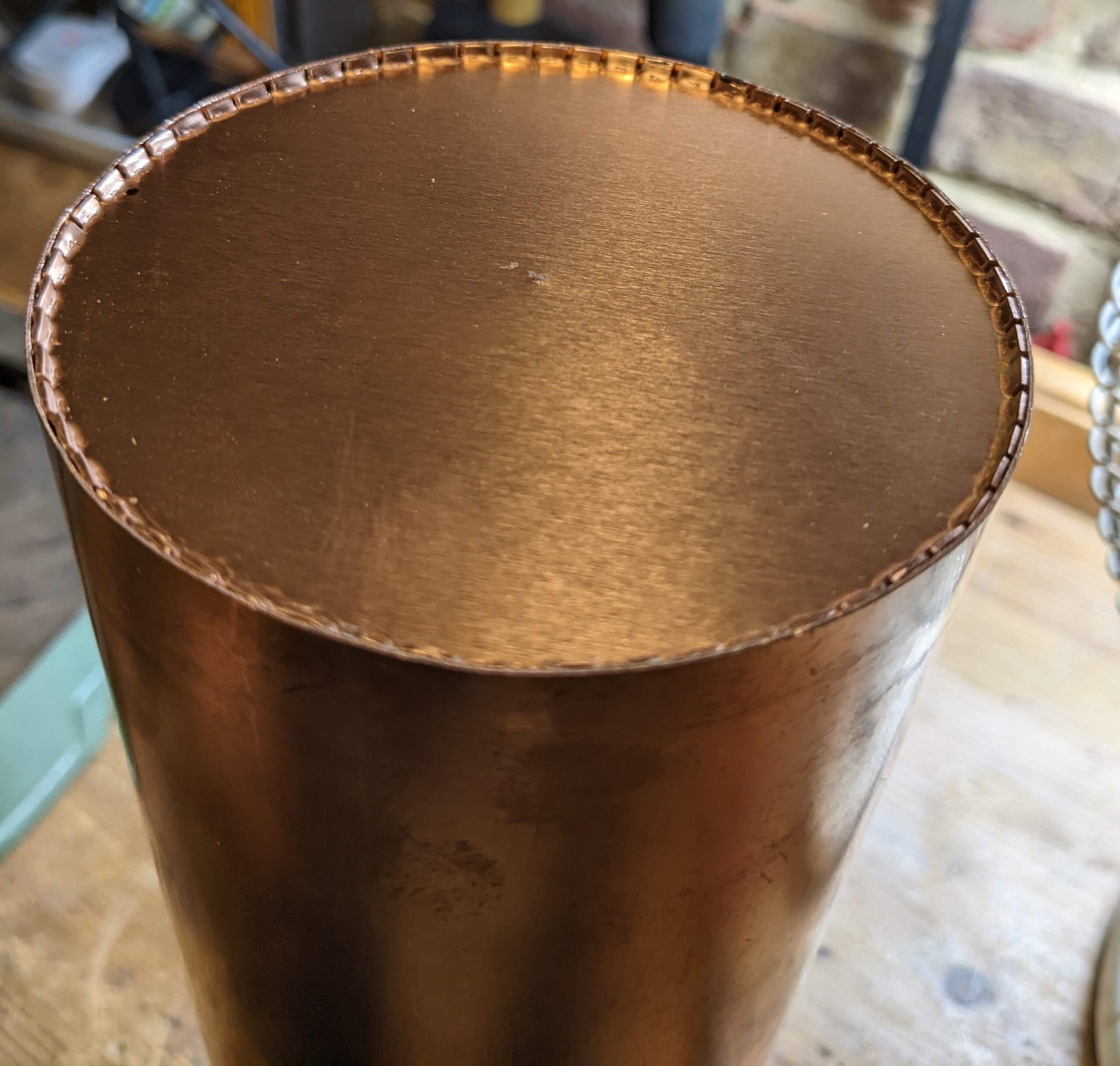
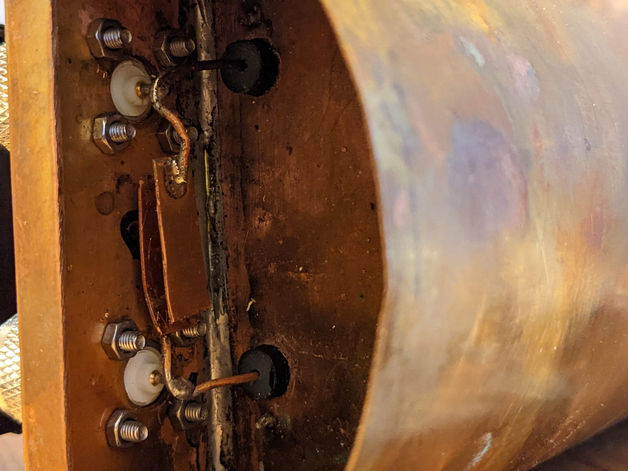
However I will not attempt to make them again, as assembly process (soldering) was a disaster. First of all, even if the copper was only 1mm thick it is impossible to solder it using a standard electric soldering iron, I had to use a gas torch and the disaster started when one part was soldered already, and during soldering the other part the first was felling off as soldering was melting.
See the table below. In theory, if theoretical resistivity for silver is one, for copper it is 1.1 and then for aluminium is 1.6 – so aluminium is roughly 50% worst than copper, but still way better than steel, iron or (surprisingly) brass.

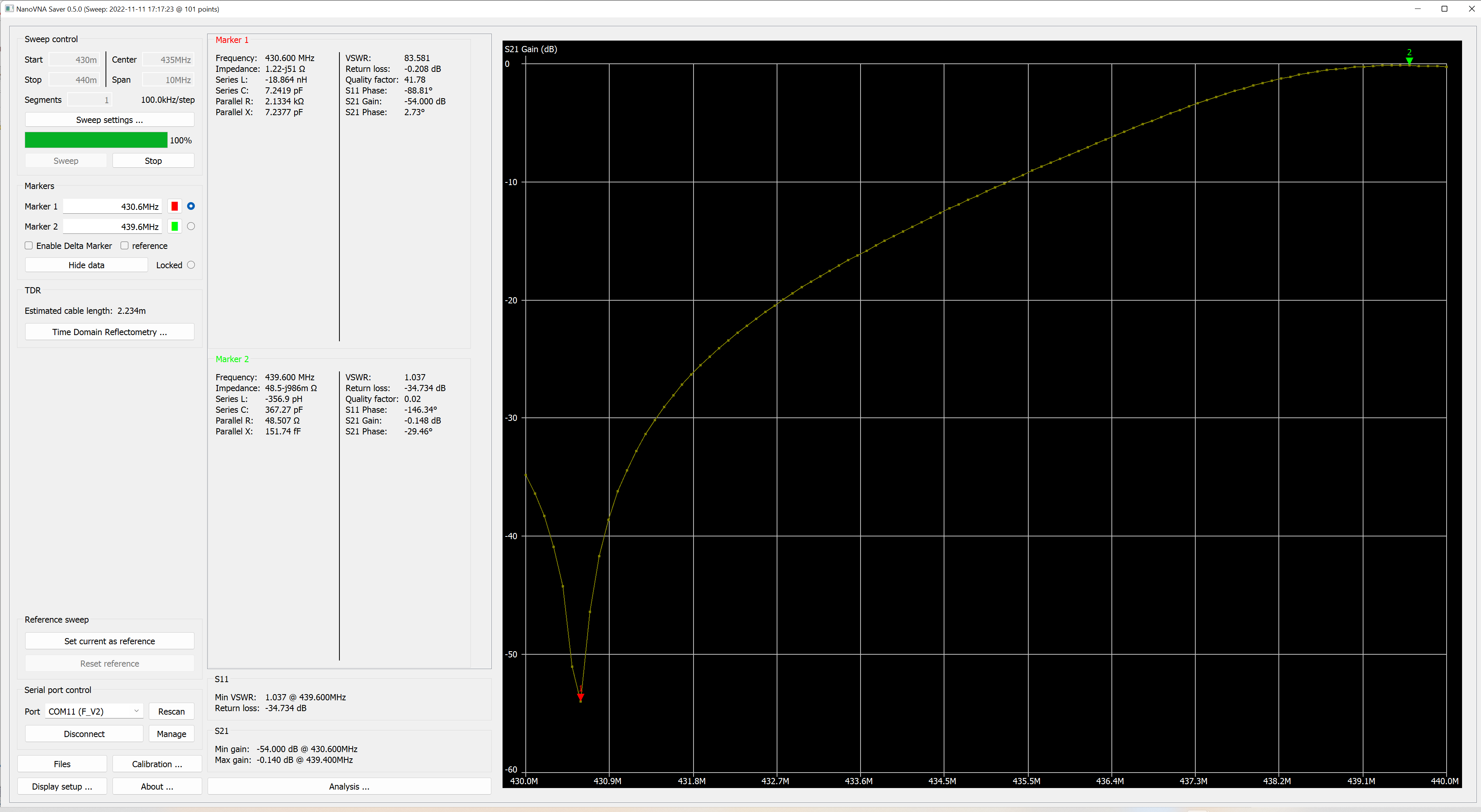
Comparing two charts – first one is copper, the second is aluminium cavity.

Hello,
I had a similar problem while soldering copper parts. During fabricating the coax 3 and 4 way splitters it was impossible to solder more than one N connector’s pins, on the copper coax central conductor. Solution was using pure leadless solder (as standard for central heating installation) for the first joint, and usual 60/40 solder for subsequent soldering. Clearly, there was enough temperature difference to prevent melting a tin based solder during latter soldering.
Incidentally, what you think about using FR4 board, i.e. PCB substrate, for part 10. IMHO it could be cheaper and easier to solder.
Regards, Darko 9A7LSD
Thank you so much for the idea 🙂