QO-100 is an amateur geostationary satellite having two transponders:
In this article we will talk ONLY about the narrow band transponder, as I personally do not have any experience yet with the digital TV which has been placed on the wide band transponder.
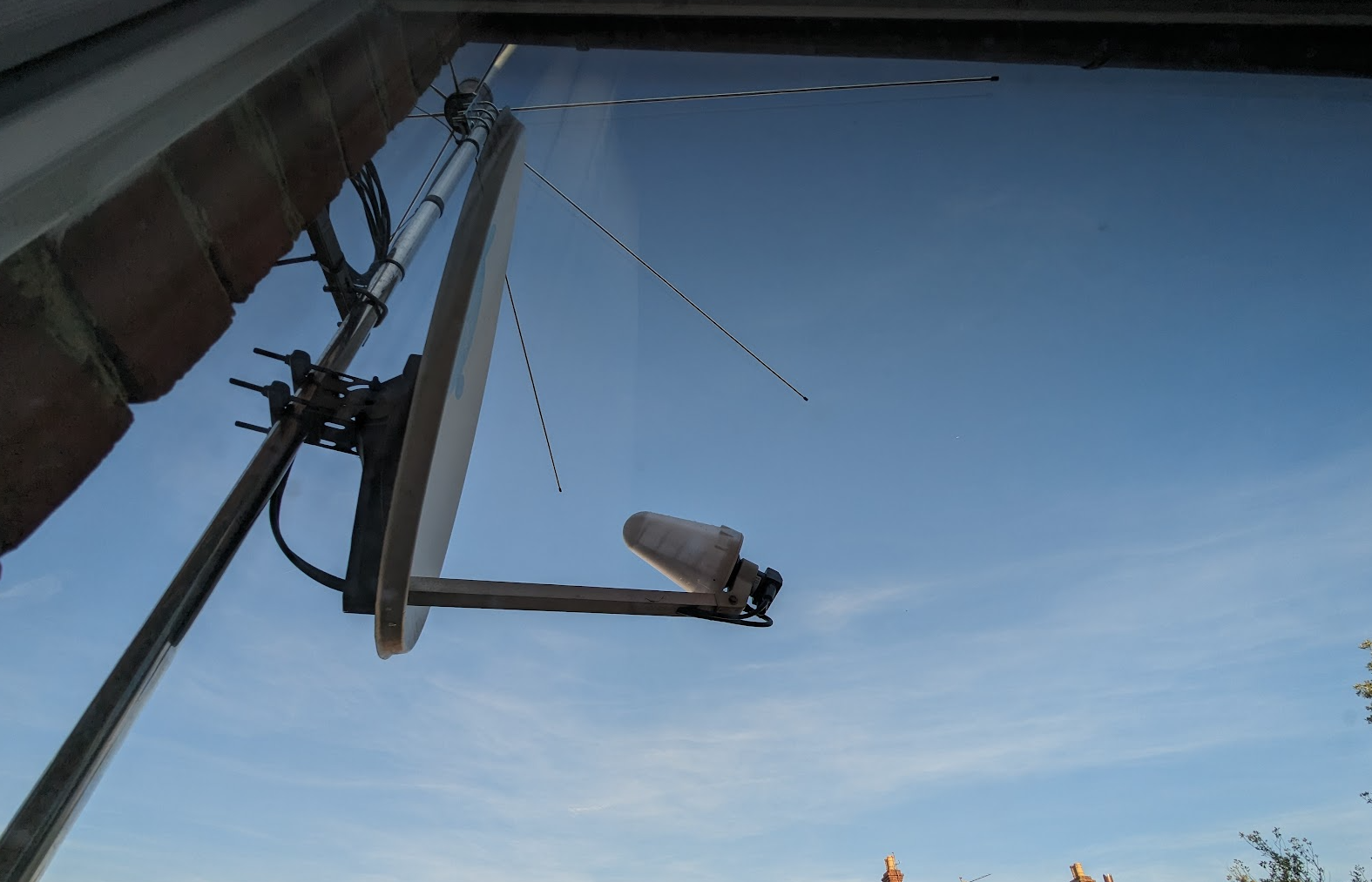
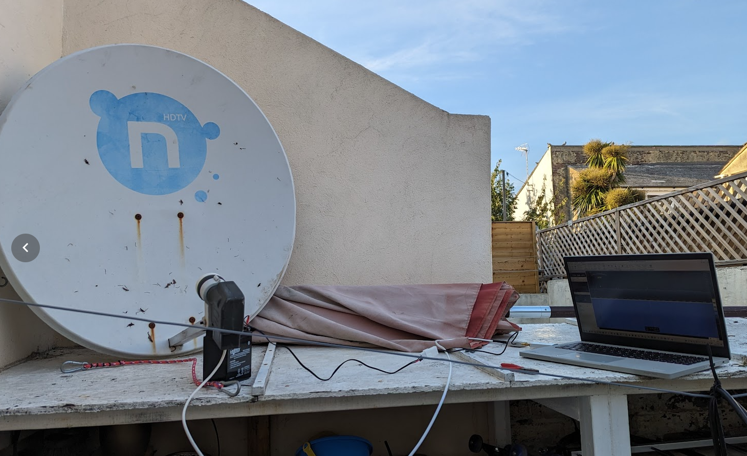
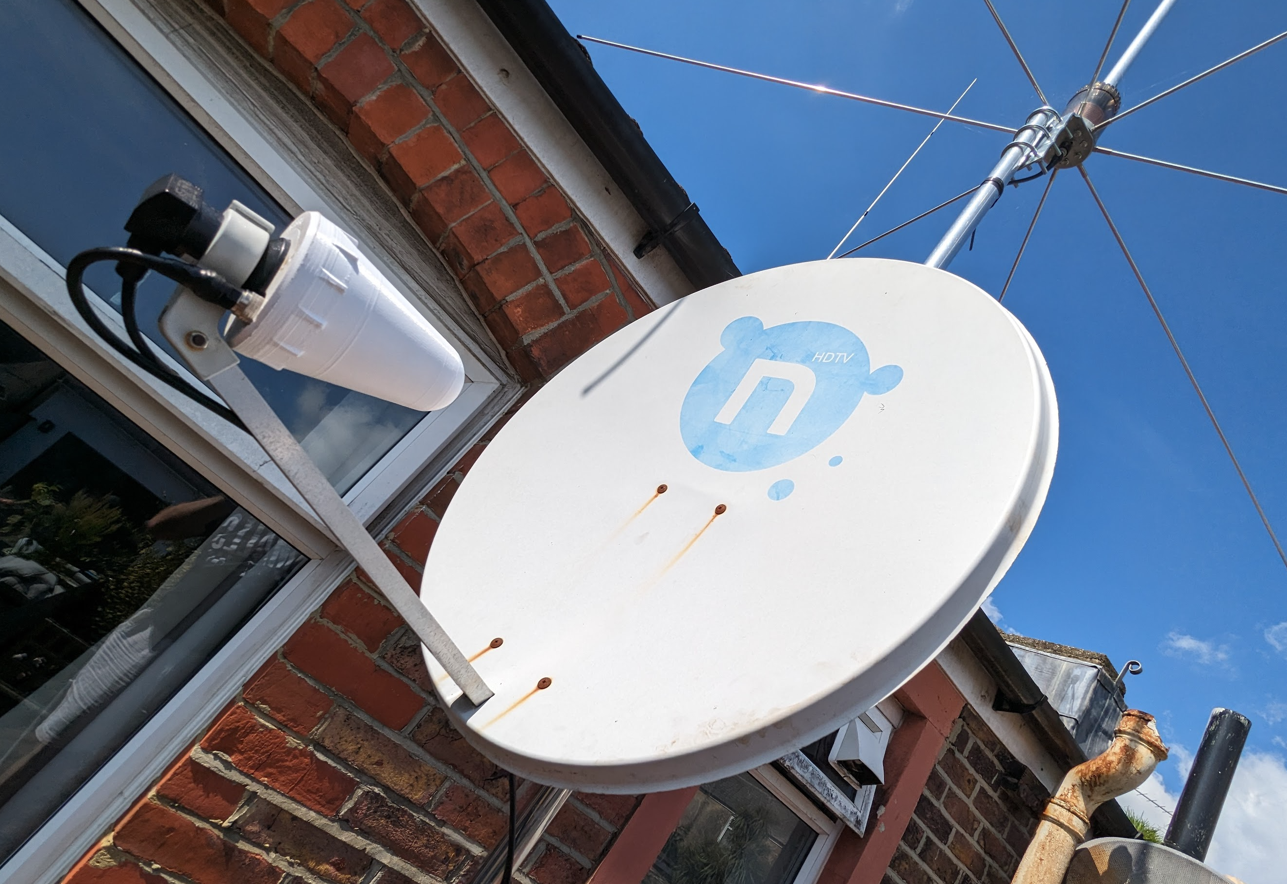
Receiving signals from the satellite is very simple – the easiest way is to use an old satellite dish – unless you live at the edge of the signal coverage, the 80x70cm offset dish will be fine. Technically you can use even 40cm dish just for receiving signals, however, 40cm dish will be too small for transmitting signals into the satellite without using a lot of RF power. With the 80cm dish I easily reach satellite with 10W @ 2.4GHz please bear in mind we talk only about the narrow band transponder! To successfully transmit DTV you will need apparently 100…200W!
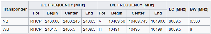
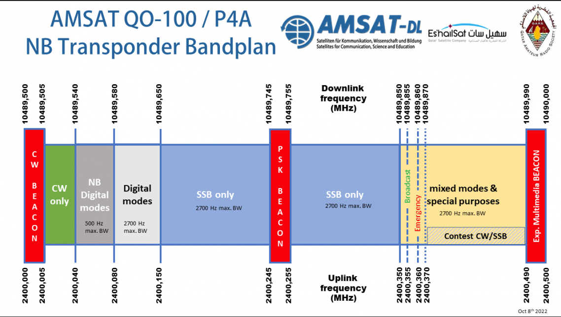
Bandplan of the QO-100:
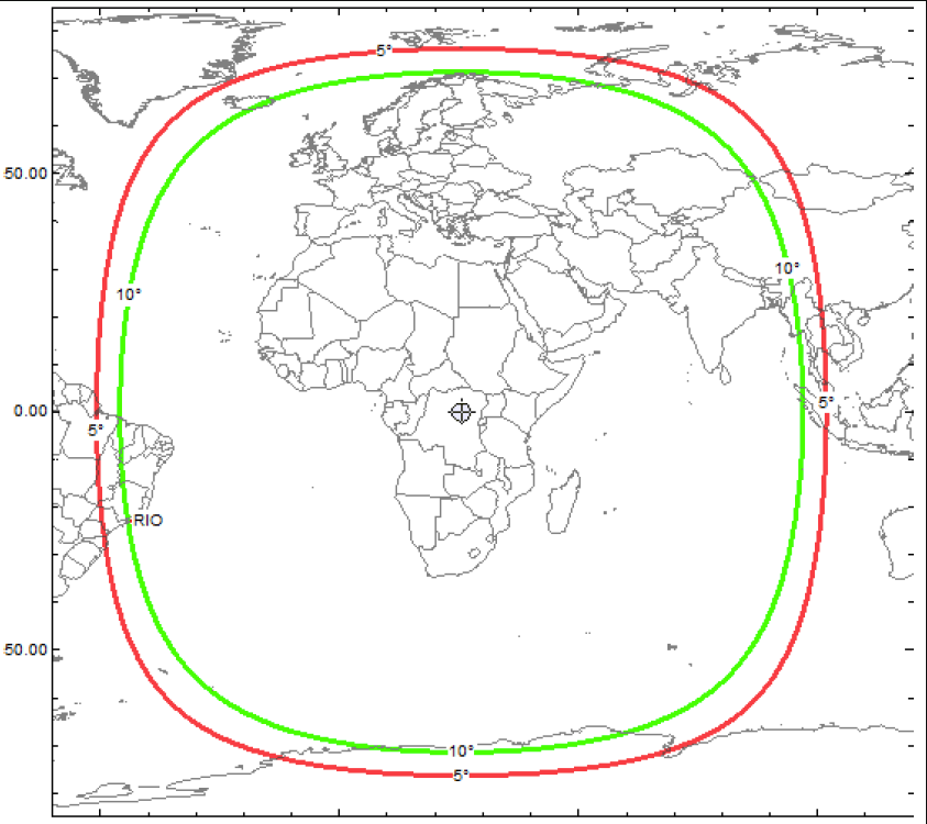
Coverage:
Let’s come back to the RX side for my station – do not forget you can try to use any different configuration with different devices! 10.5GHz signal is receiving by the LNB which converts 10.5GHz into 739.5MHz band. It means most ham radios won’t be able to receive this frequency. Many ham radio operators buy down converters, to get the signal from LNB converted into 10m, 2m or 70cm or 23cm band. However that solution is relatively expensive – £200

The image above shows downconverter from DX Patrol. Pros: you can receive on 10m, 2m, 70cm and 23cm. Also it comes with very stable 10MHz TCXO which can be easily optionally replaced with the external, GPS Disciplined Reference Oscillator (GPSDO) which is even more stable. Cons: if by mistake you press PTT into the downconverter, you will damage it easily!!
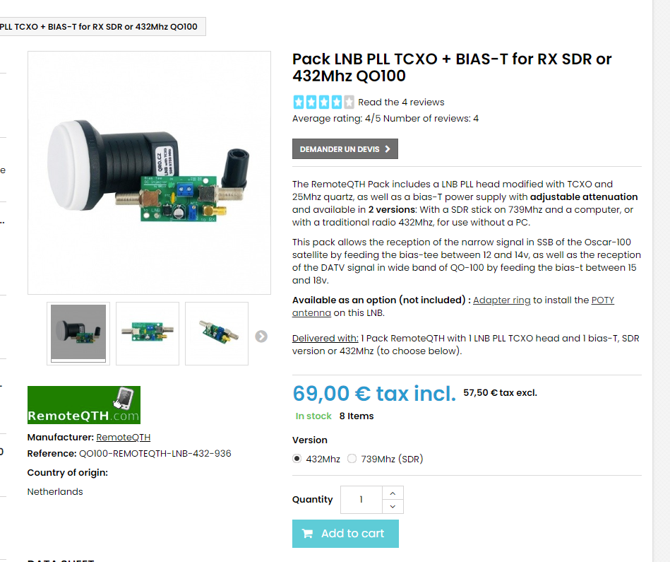
Another option (see image below) is a very stable LNB – see below – with original frequency RX at 739MHz or with modification so you can receive the signal using a standard SSB 70cm transceiver. Pros: relatively cheap, cons – 70cm version will be damaged if you accidently PTT into it.
My favourite (for now, it may change!!) option is LNB with bullseye LNB:
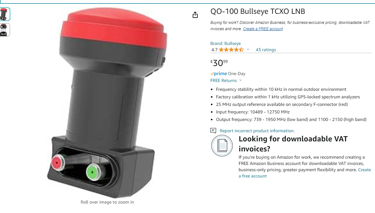
The LNB above is a very stable LNB perfect fir receiving QO-100 satellite signals. Pros: perfect, cons – I have not found any 😛
Now, what device do I use for receiving? The RTL-SDR v3 receiver:
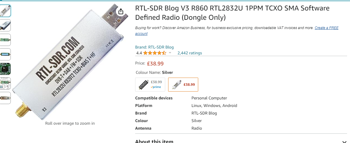
In the videos below you will see how the receiver works with the standard and with a special BullsEye LNB.
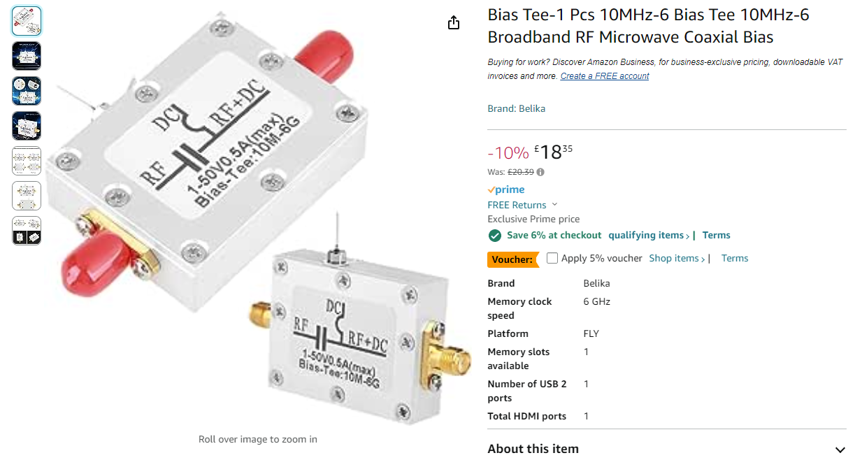
However, no LNB will work correctly without getting some voltage – LNBs needs power 🙂 To provide a power, I use a very simple device called Biass Tee – technically it separates a DC12V from RF signals. One side is connected to RTL-SDR and the other side into the LNB. LNB will receive 12V voltage to work in vertical polarization. If 18V is sent, the LNB will switch into the horizontal polarization – but we do not need it.
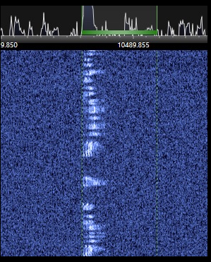
Now it is a very important comparison. Why LNB stability is so important? First picture shows my test dish with a standard LNB without any TCXO oscillator. It is actually possible to understand the voice but it is very uncomfortable. Just under the image you will see the video too:
The other image below shows the same antenna, the same set up but with a BullsEye LNB – a massive difference!!! Watch the video!!!

Small update.
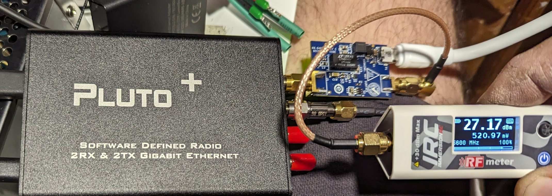
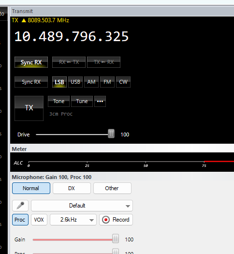
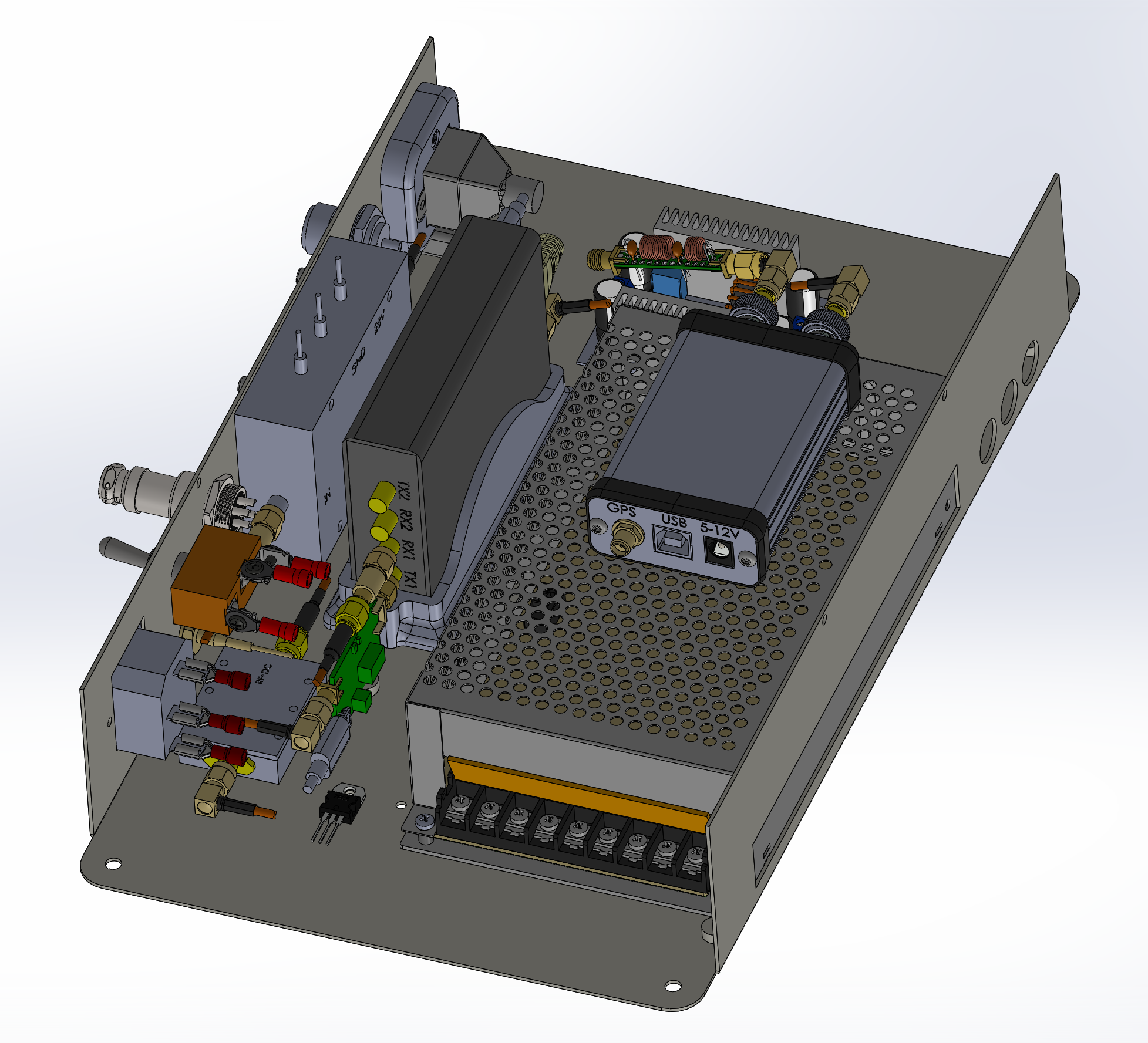
To be able to transmit into the satellite, I decided to buy a SDR TRX called Pluto+:
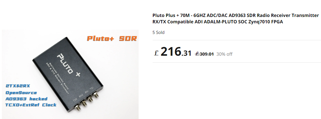
It is an amazing SDR RTX working from 70MHz up to 6GHZ!!!
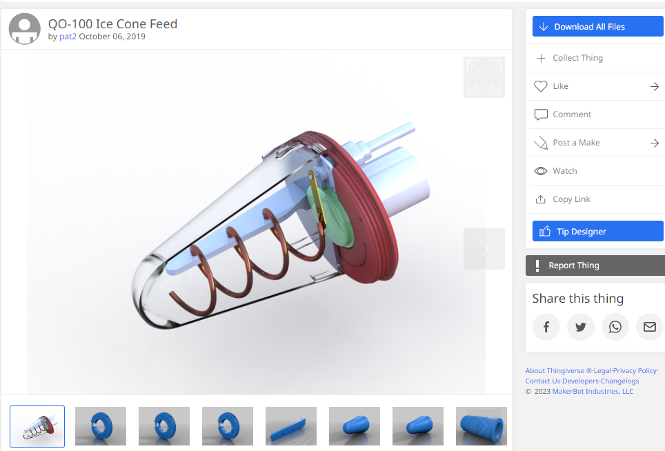
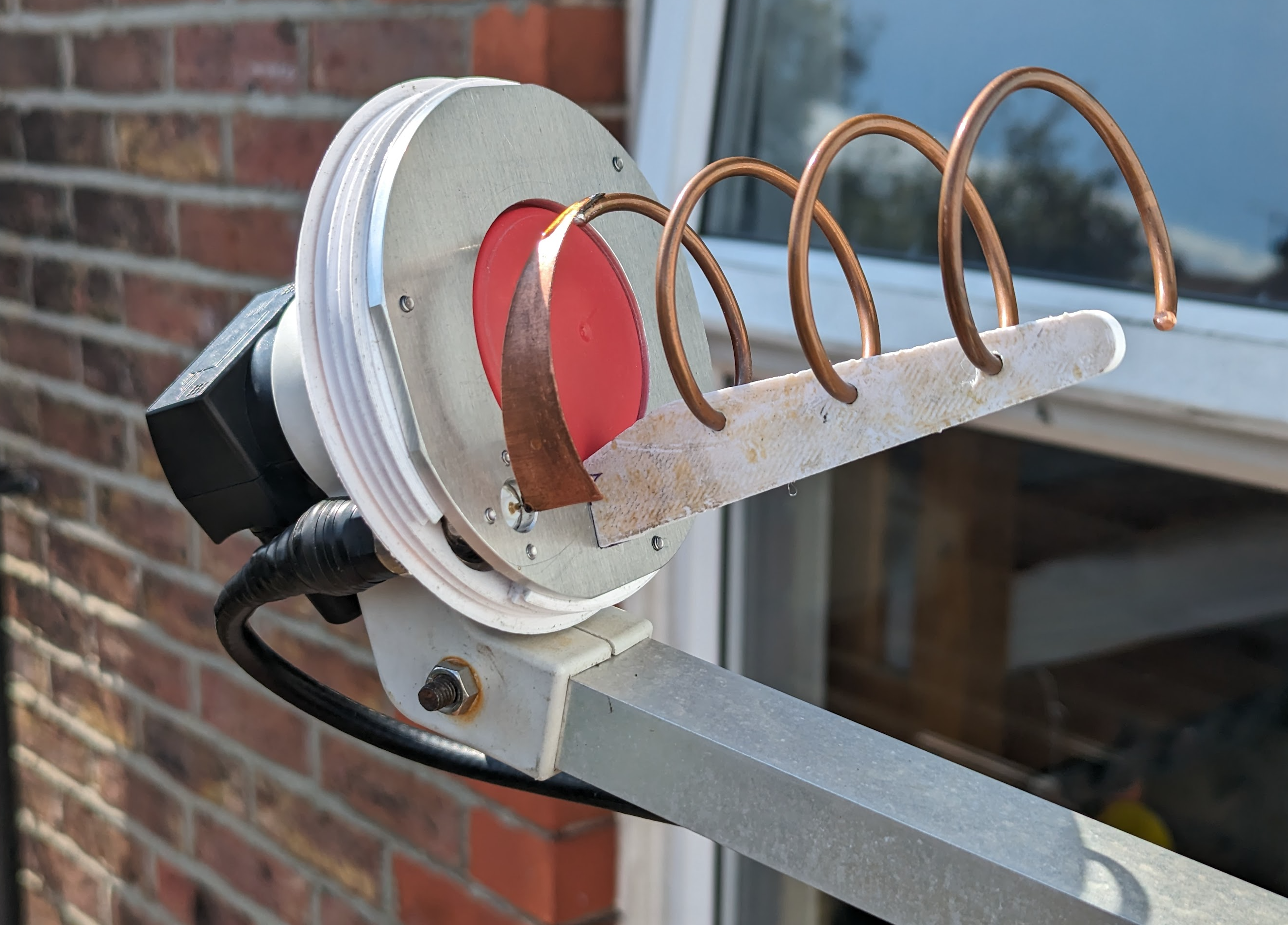
As the transmitting antenna I use the same satellite dish as for receiving, but on the top of the LNB I added a 3D printed helical 2.4GHz antenna (well, the housing is 3D printed).
Link to the project is here: https://www.qrz.com/db/DC8PAT and here: https://www.thingiverse.com/thing:3899461
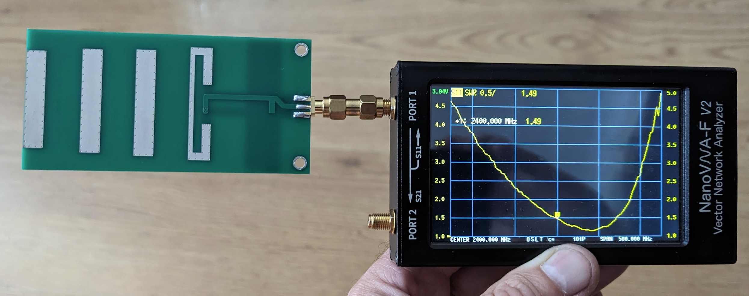
Optional to the cone antenna is a Yagi 2.4GHz antenna printed on the PCB – see the test HERE. Please be aware that if you decided to use the Yagi antenna, as the result of using a linear polarization (doesn’t not matter if you decide to use H, V or angled polarization) you will loose 3dB, which is not a disaster for QO-100.
On my computer I use SDR Console software:

TX Part of the station:
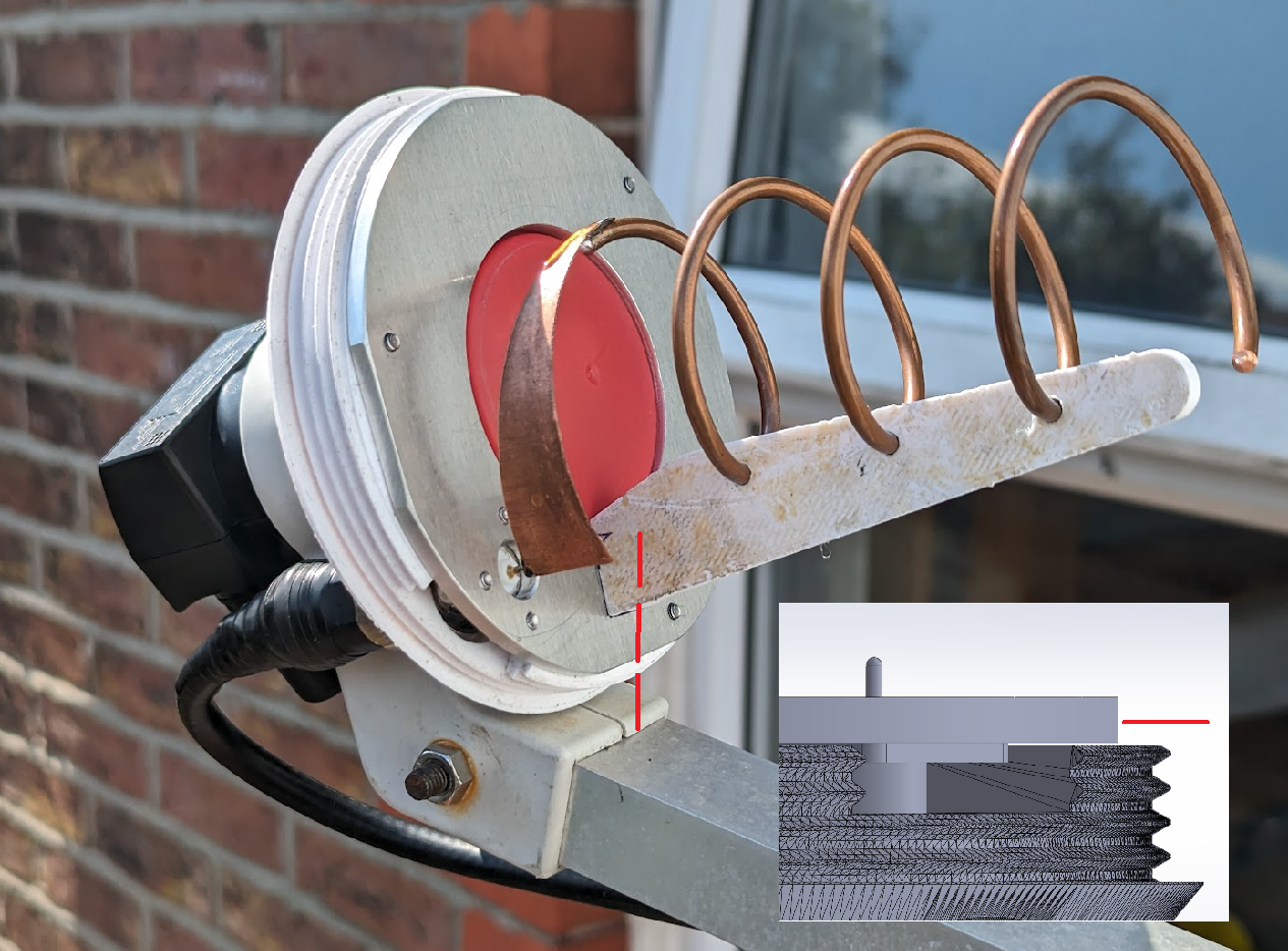
I decided to use a cone 2.4GHz circular polarization antenna (RHCP) which will sit in the coal point of the disk antenna together with LNB.
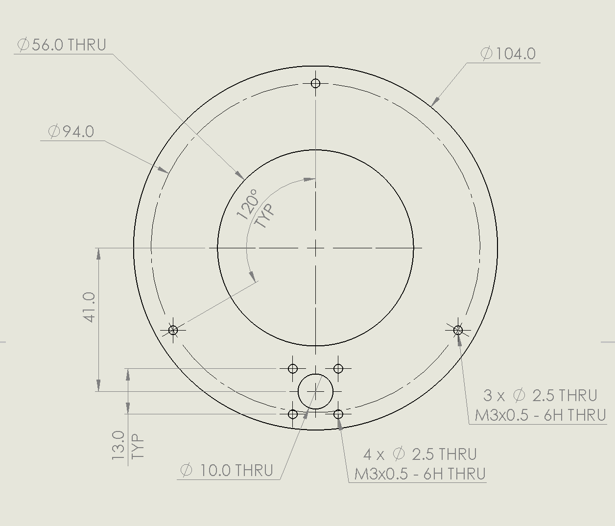
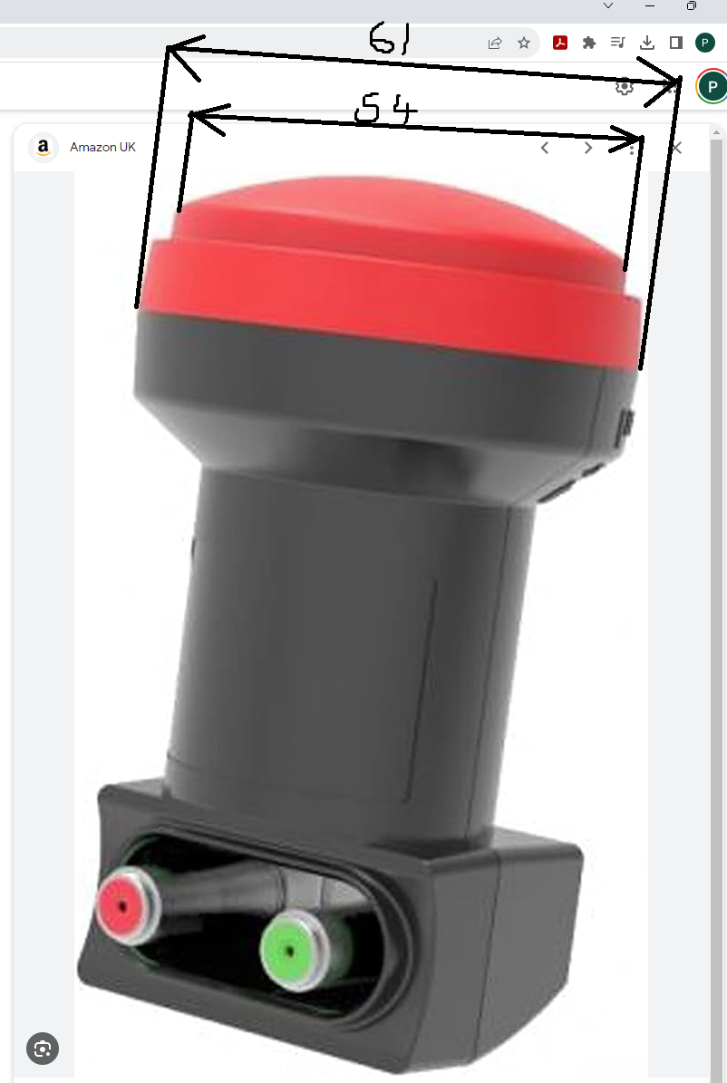
I use the bullseye LNB so be aware that the original design of the aluminium reflection need to be slightly modified – pic below shows original drawing, I modified the original 48.00 dimension and I made it 56mm as the LNB red cap is 60mm, but the very small recess at the top is 54mm and it nicely goes into the bigger hole in the reflector. 56mm (not 54mm) is required for tolerances reason. The base provided by the author (DC8PAT) is good: reflector_support_61mm_LNB.STL

Cone 2.4GHz antenna added:

It is a very good idea to use a pure silicone grease – it makes the thread operation much, much smoother!!!
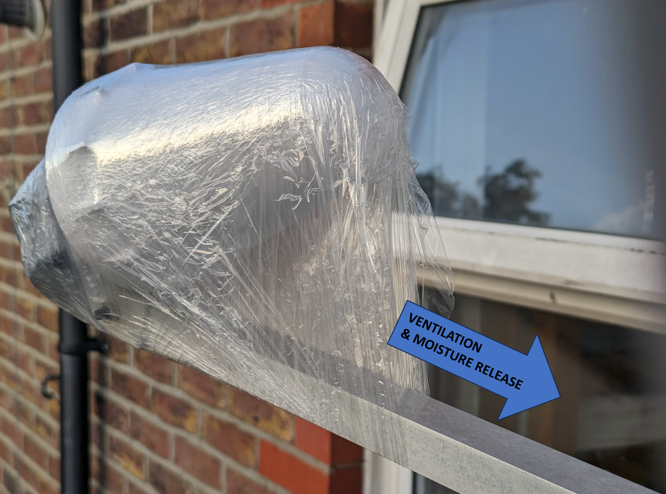
After analysing the built of the DC8PAT cone antenna I realised the housing is not protected from getting the water inside. The issue is the gap around the N socket. If the socket is positioned right at the bottom, any water getting inside or just the condensation could go outside through the gap, which actually creates the issue, as you cannot position the N socket at the bottom, as it will clash with the LNB’s arm. So the solution is to drill a drainage hole exactly in the right place – but because I have already mounted the cone and I was too lazy to remove it, I just decided to use a stretchy film 🙂
UPDATE:
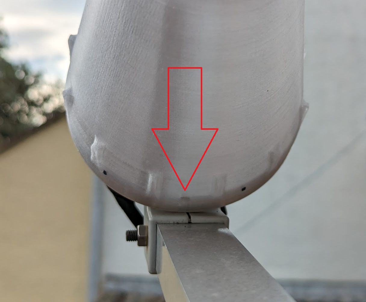
The plastic film work fine, but it is ugly!!! I decided to drill a diam. 5mm drainage hole in the cone, centre of the hole roughly 13mm from the edge of the cone. Red lines show the position of the hole. It is a good idea to tight the cone first to establish where to drill the hole so it will end up at the bottom of the cone, when it is tight.
Receiving 10GHz frequency.
You need to restart your program now to be able to see 10GHz band.
Synchronisation.
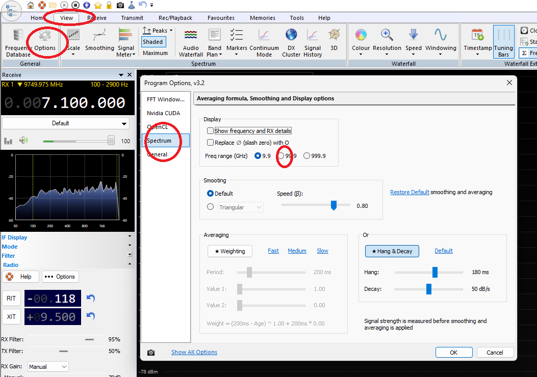
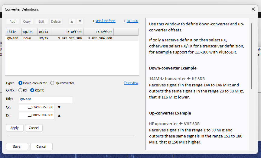
Even very stable Bullseye LNB and Pluto+ they drift during the day time due to the temperature changes, even 3…4kHz!
I adjusted the software converter to match the beacon at 10.489.750.000 Hz in the morning time, few hour later I found it moved by 275Hz (not too bad, as yesterday it moved 4kHz).

The expensive solution is to buy an external GPSDO (GPS Disciplined Oscillator) or to use a beacon which is transmitted all the time at exactly 10.489.750.000 Hz.
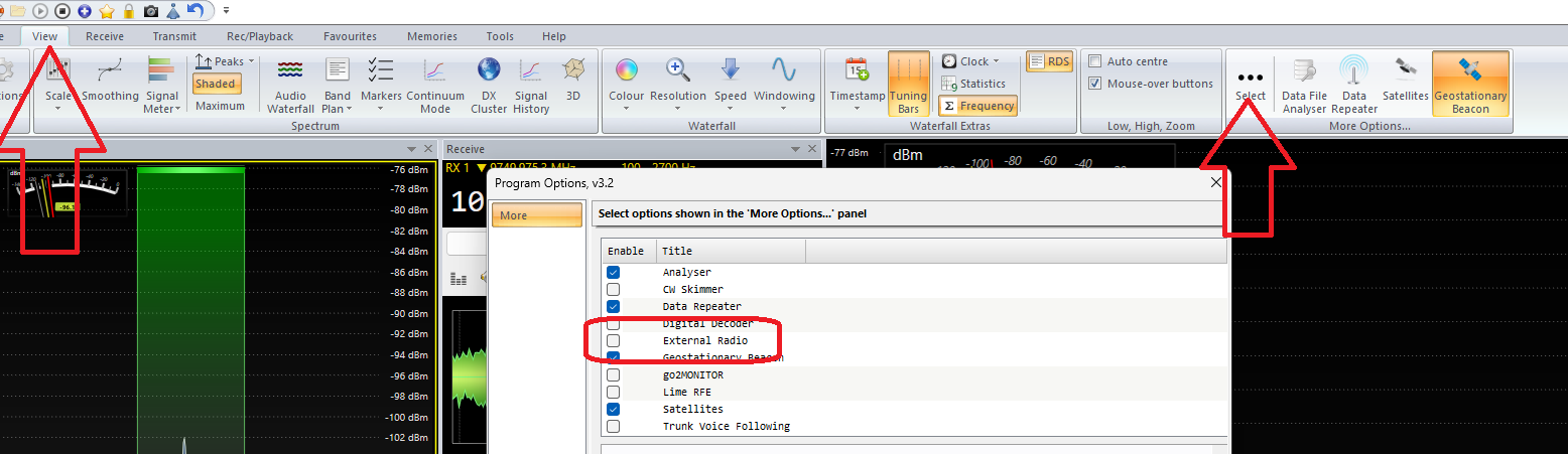
To do it you need to go to: view tab, and then geostationary beacon:
If you do not see that option, go to:
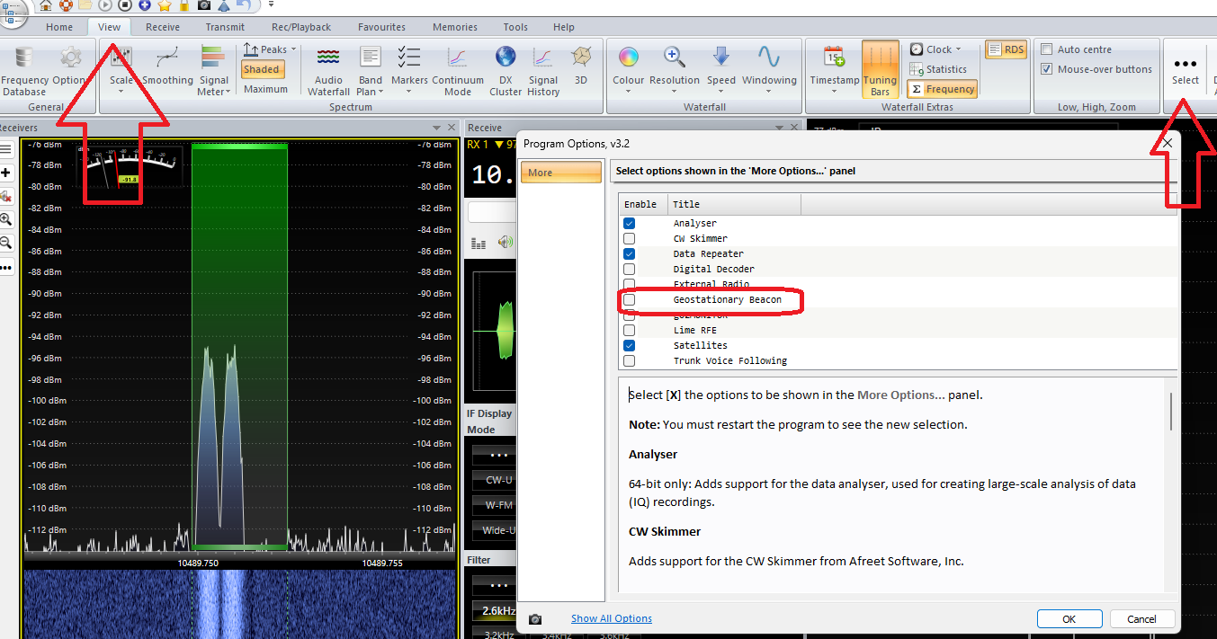
and select the Geostationary Beacon option.
Activate the option by pressing Play symbol
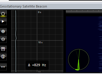
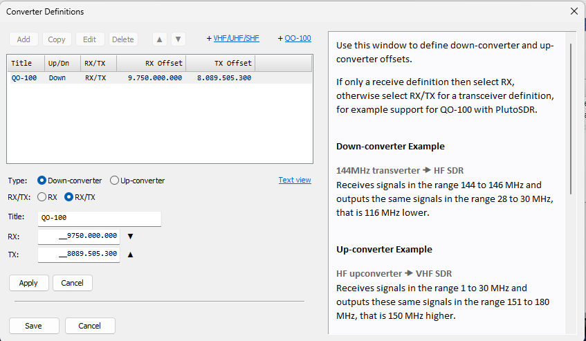
The small green clock shows the actual correction (it is showing now +829Hz).
However, I still keep my corrected settings, as they are close to the reality:
or
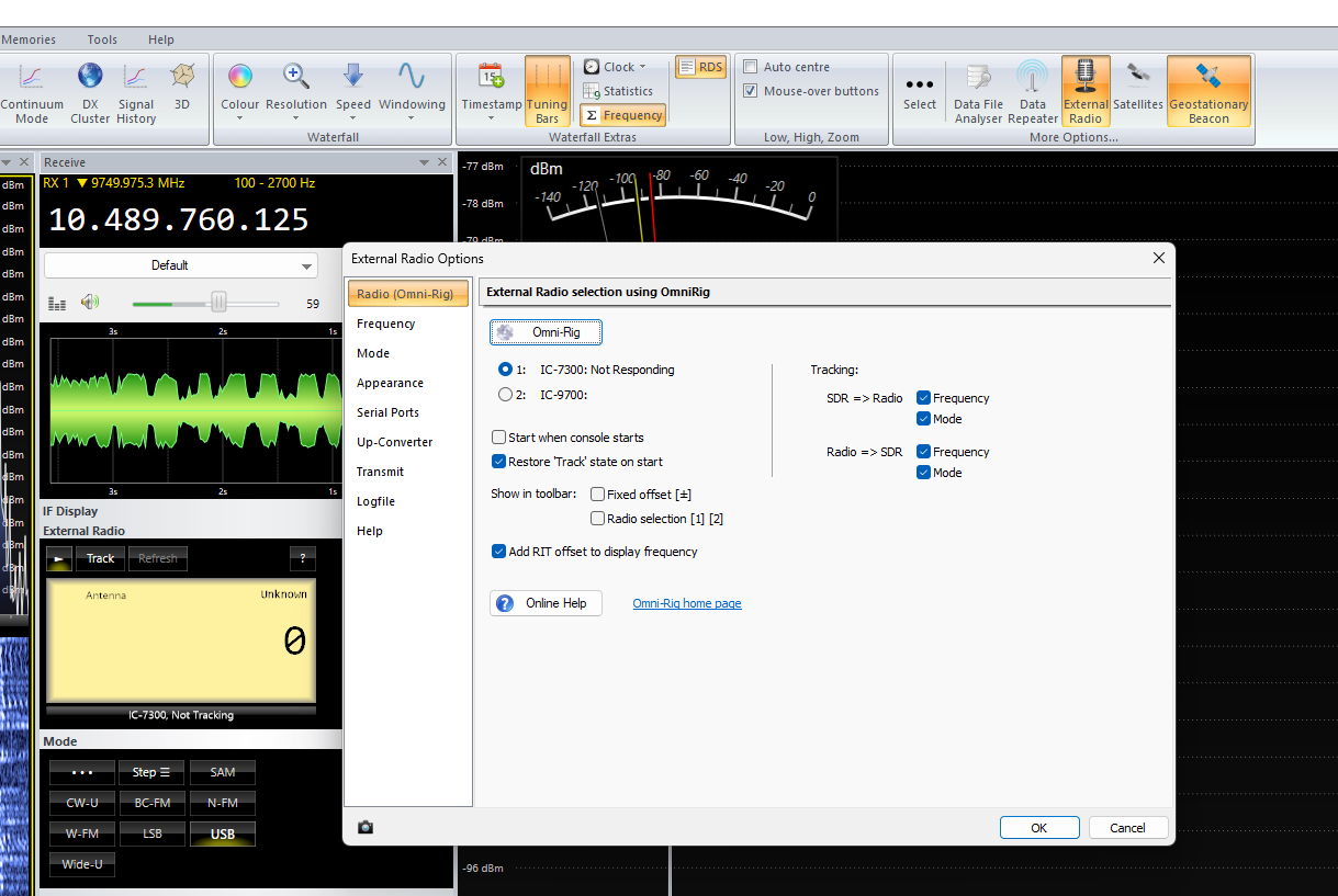
You can also synchronise an external radio, preferably through OmniRig. To get this option, do as shown below:
and then the option will appear here:
Some people may wonder what is a impact of the plastic element sitting at the from of the 2.4GHz antenna.
Please note so far I did a test only for 2.4GHz band, I will compare the 10GHz at some point later, however people say they do not see any impact or some people say it is not more than 2dB. Please note that for the TX I still use only 500mW as I am still waiting for sg-labs amplifier 🙂
Please note, sg-labs makes v2 and v3 20W 2.4GHz amplifier. The first one needs 0.4W RF input to get 20W RF power out, the v3 needs only 40mW RF input, as it has been equipped with internal preamplifier! Also v2 has no VOX, v3 comes with VOX. So I will have to add 15dB attenuator, as I ordered v3 amplifier.
Results for 2.4GHz:
No cone:
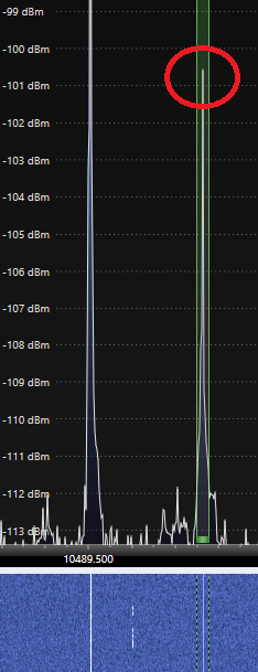
with cone attached:
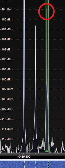
So no measurable impact at all. In fact the signal varies +/-1…2dB all the time so I tried to catch the average measurement but it was difficult. Actually it looks like a signal level is better with the cone cover -99dBm where no cone was -100.5dBm 🙂 🙂 🙂 Please do not forget these very low results are because I use only 500mW !!!
Amplifier with Pluto+
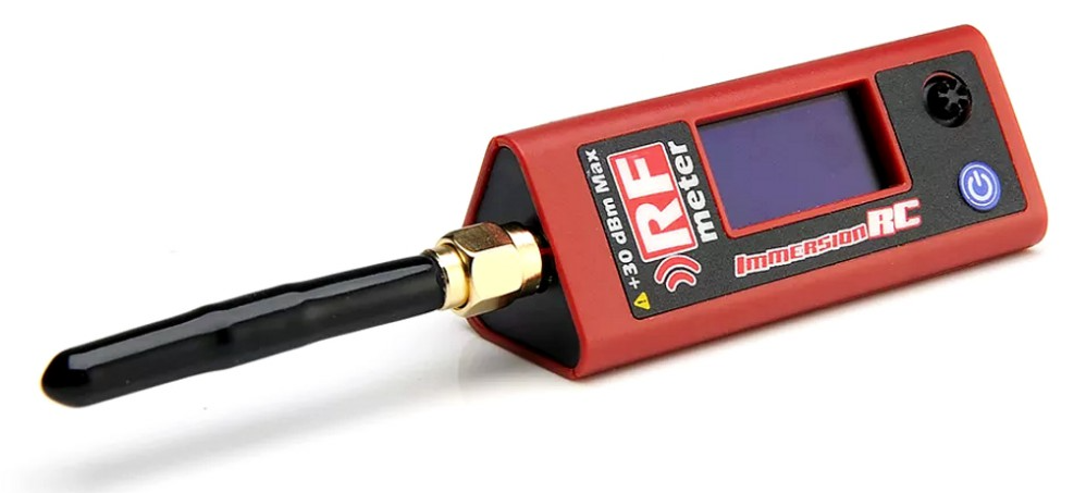
Well, where to start. First of all, to stop being blind, I bought a very useful tool: RF power meter up to 6GHz. Usually these devices are very expensive. However, the small exception is ImmersionRC RF Power meter V2.
I quickly found out that the maximum RF transmitting power coming out from Pluto+ is 5.7dBm = 3.7mW:

The PA (power amplifier) which I ordered from Bulgaria from sg-labs has not arrived yet (however I should get it in the next few days).Anyway, I know, the Bulgarian PA gain is 27dB – the maximum 20W can be achieved by powering the PA with 40mW @ 28V.
So as you can see, if I power Bulgarian PA with only 5.7dBm = 3.7mW (5.7+27=32.7) I will get 32.7dBm = 1.86W which will not be enough to make SSB QSO.
What to do? I need preamplifier.
I bought CN0417 2.4GHz power (pre)amplifier.
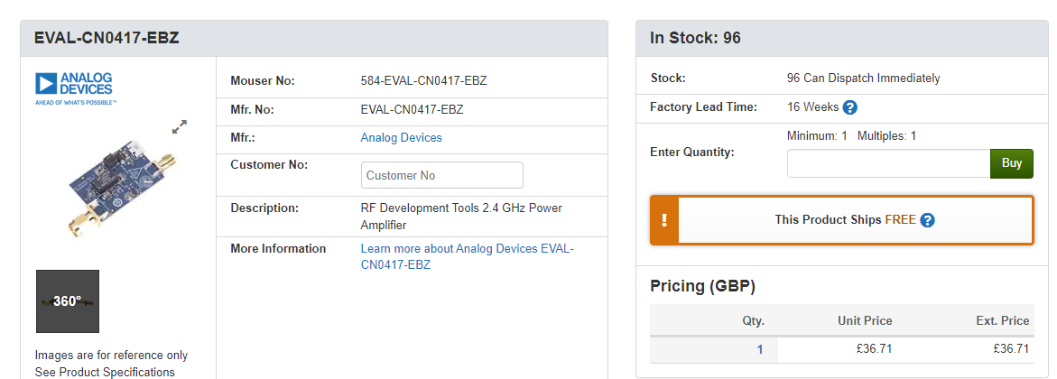
The amplifier, according to the spec sheet provides 20dB gain:
So my 5.7dBm + 20dB = 25.7dBm which should be 371mW. Surprisingly I achieved 27.17dBm which is 520mW. It means the preamplifier gain is actually 21.47dB.
So my 0.5W signal at 2.4GHz let me already transmit to the QO-100 satellite with quality good enough for CW but it is not good enough for SSB QSO. When I try to listen to myself using 0.5W, I know there is somebody talking (me, hi) but it is too difficult to understand. However it indicates good quality of my antenna system. If here is anything wrong, 0.5W would not be enough to reach QO-100!
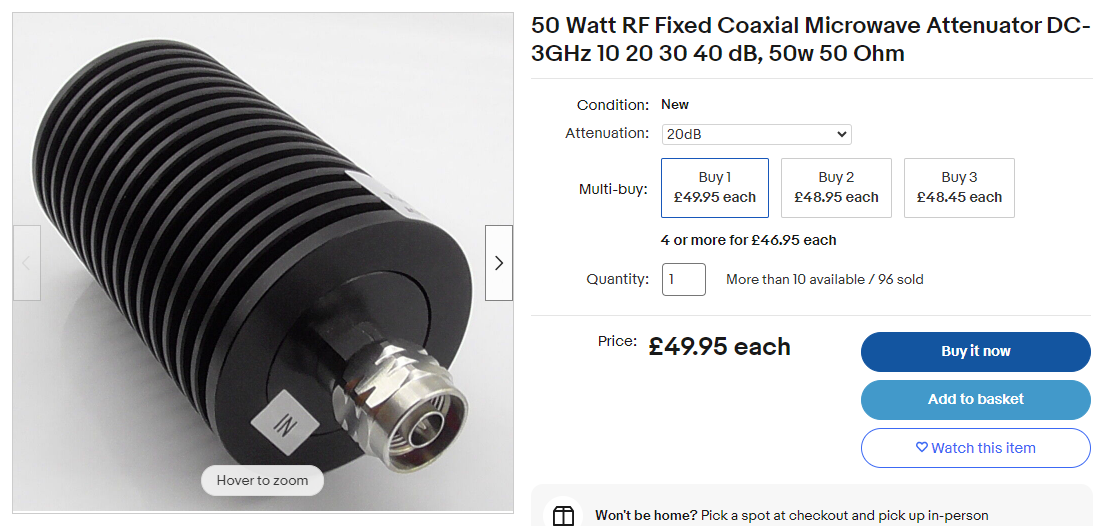
So, now we have a problem. If I connect 500mW to my final 20W PA it will just get damaged. So, I bought from “my friends” a small 15dB/2W/8GHz attenuator:
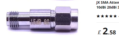
It brings 27.17dBm down to 12.17dBm which is 18.6mW.
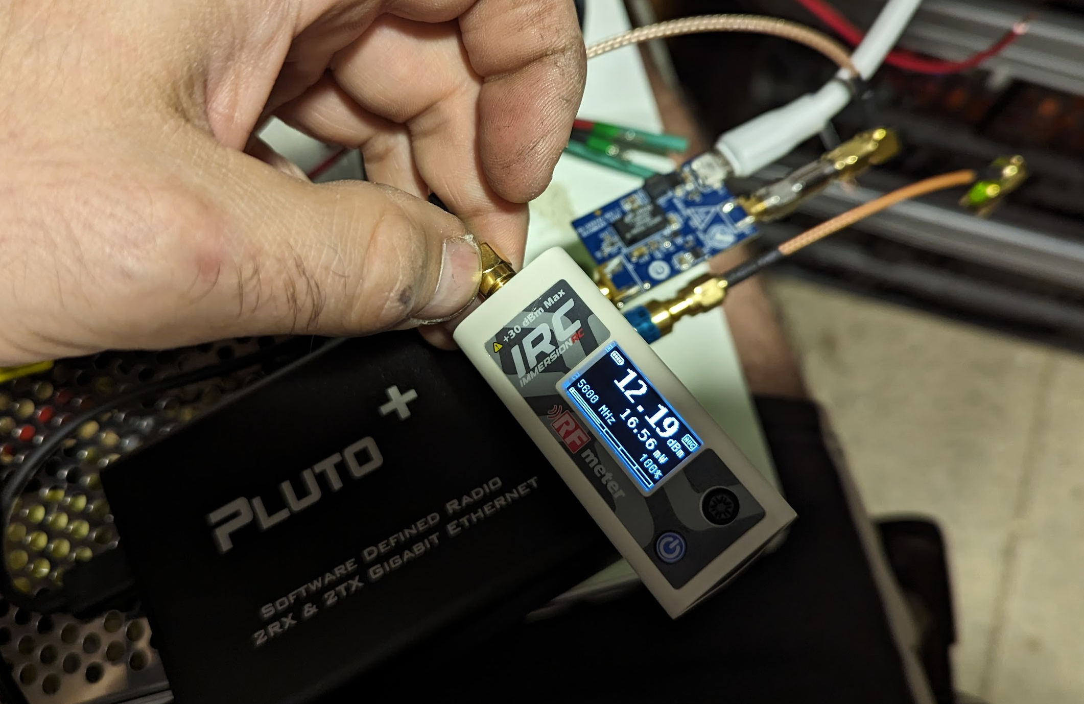
The reading is actually 12.19 (very accurate attenuator anyway) + 27dB gain from the main PA = 39.19dBm which makes 8.3W and this should be a perfect power for QO-100. If it is not enough and I need for example 15W I will change 15dB attenuator with 12dB attenuator.
Now some people may ask some important questions. Question 1 – why I put the attenuator after the preamplifier – It is a bit of RF power wasting. True. However if there is anyhting wrong with preamplifier and it gets eg. looped it will push all available power! Safer to keep attenuator after the preamp then. Another question is why I just cannot simply turn down power in Pluto+ itself, using drive slider?
Well, sometimes Pluto generates RF spikes which will cause damage to the PA – confirmed from sg-labs. So again, safer to keep maximum power and just degrade it with attenuators.
I just would like to repeat this info again, sg-labs makes v2 and v3 20W 2.4GHz amplifier. The first one needs 0.4W RF input to get 20W RF power out, the v3 needs only 40mW RF input, as it has been equipped with internal preamplifier! Also v2 has no VOX, v3 comes with VOX. So I will have to add 15dB attenuator, as I ordered v3 amplifier.
I have decided to buy also 20dB 3GHz 50W attenuator. It will let me measure the power coming from the main PA – the maximum power input for ImmersionRC device is 30dBm=1W.
Big day! Today (26.09.2023) after waiting for over a month, I received the PA from sg-labs from Bulgaria. It works perfect with 15dB attenuator as predicted.
Design…
…and real life so far:


…and a design of the portable station:

…and the real life 🙂 :


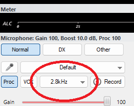
When I started my the very first QSOs I found a strange problem and it took over 2h to find out what was wrong. When I was transmitting only left side of the audio spectrum was filled with my voice:
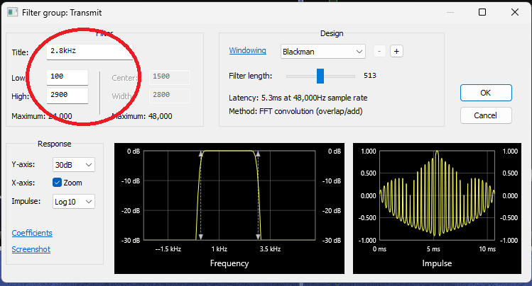
So my voice was very “bassy” with to trebles at all. Of course the first step was to check if I use correct audio filter – yes, it was correct:
also I checked if everything inside of the filter was set up correctly:
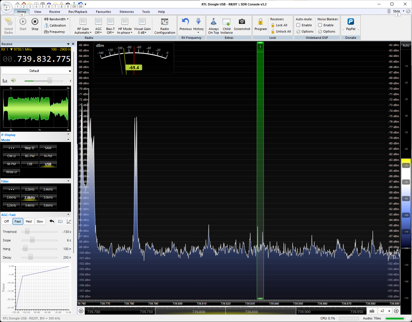
After 2h I finally found what was wrong. I looked at the top right corner to find that the audio was very limited to only 1200Hz!!!
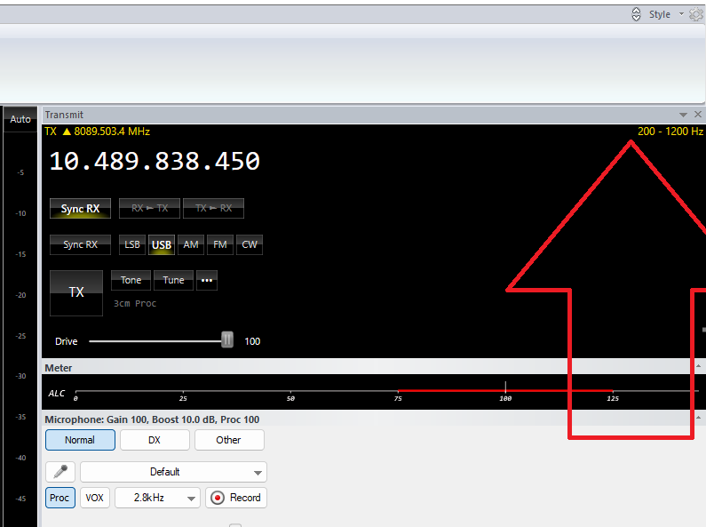
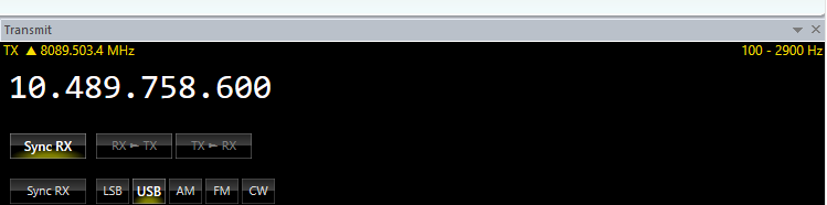
I cannot explain why it happened. My filter was set up correctly. What helped was to switch to any different filter and they switch back to 2.8kHz which corrected the setting at the top right corner:
Just one more thing – do not get confused. When you use linear low orbit SSB satellites, you usually receive signal using USB and transmit using LSB. QO-100 is different – you receive AND transmit using USB.
I hope my article was a bit helpful. Thanks for reading.
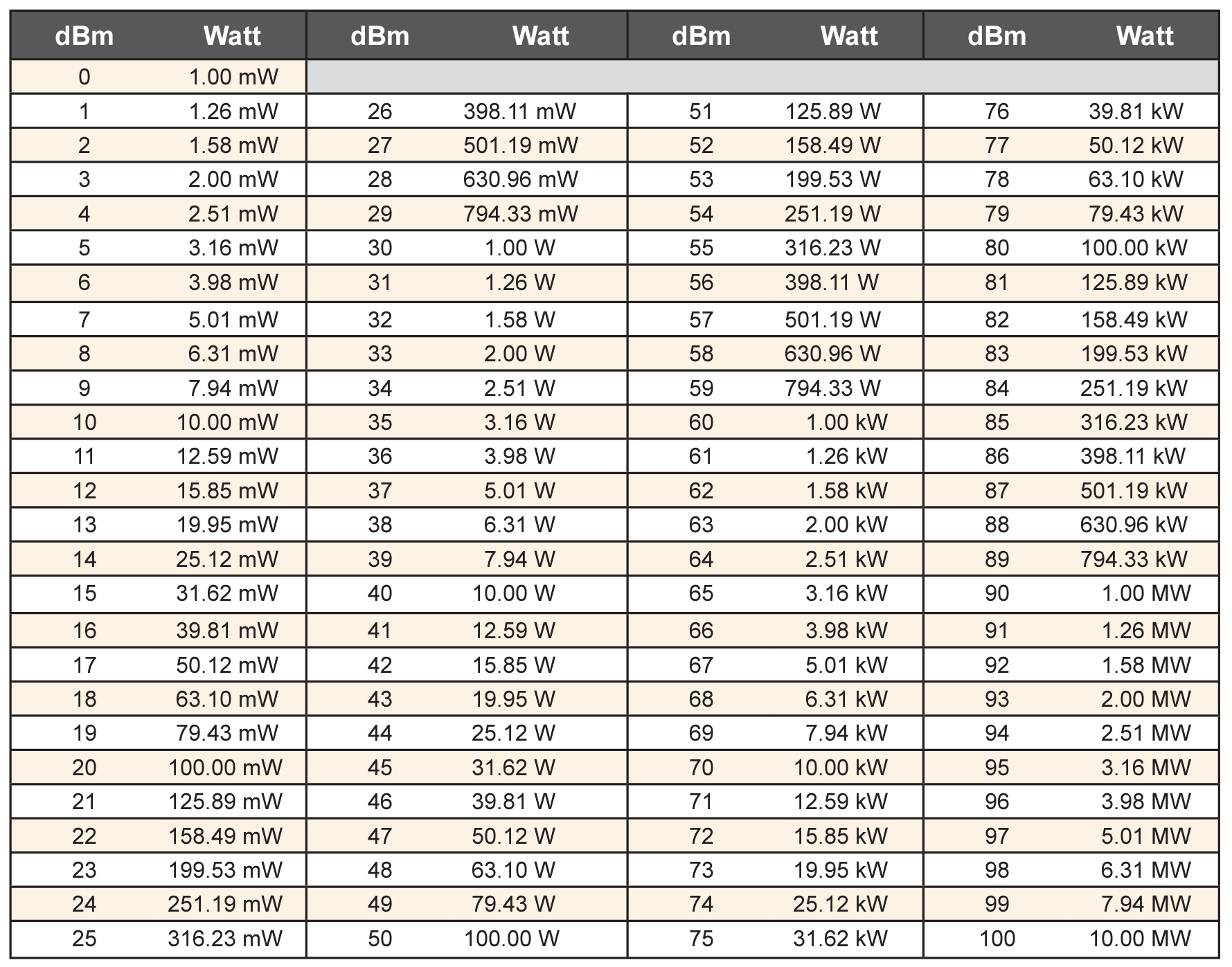
Very helpful table:
you have yout tx offset shifted by 300Hz … but it is better to set the ppm error in the pluto settings (shift xtal frequency by 5Hz)
Hi, yes, I know, and despite of using GPD-DO there is still aboy 150Hz discrepancy between RX and TX and I wonder if this is a problem with my Pluto TX part or it is an internal temperature deviation from LNB, despite feeding it withGPS Do too. Anyway, I was going to do the investigation and I had no enough time and I gave up. Actyually thank you for reminding me that, I will try to tune my Pluto to the best QRG. Do you mind please to remind me how to do it (what command)? If not, I will try to google. Many thanks 🙂