This article is about flashing Motorola GM3xx series with a new firmware, so it won’t be about CPS programming. If you decide to follow my procedure, you do it on your own risk, as it is possible to corrupt (brick) the radio firmware so in many cases it won’t be usable anymore without professional help.
Before I start I would like to say thank you to Derrick Mulvana M1AKH who helped me with some confusions on that project.
About being professional: I am not a professional radio engineer however I always try to improve my knowledge and just always try to have a fun with my radios. Few months ago on eBay I bought 4 x GM360 and 2 x GM340. I used 2 of them to run a GB7FT DMR repeater in Portsmouth and 2 other ones are in a test repeater now. Other two are for testing and playing as well. After buying the radios I found very quickly each of them use different firmware, so each codeplug needs to be in a different version. I ended up having codeplugs v8, v6 & v4! The corresponding firmware was at R03.13.00 (v8), R03.11.02 (v6) and R03.01.27 (v4). Theoretically it is nothing wrong, as each CPS (cpg) file is assigned to a specific radio. But as I am a bit pedantic person and I really wanted to make files systematic.
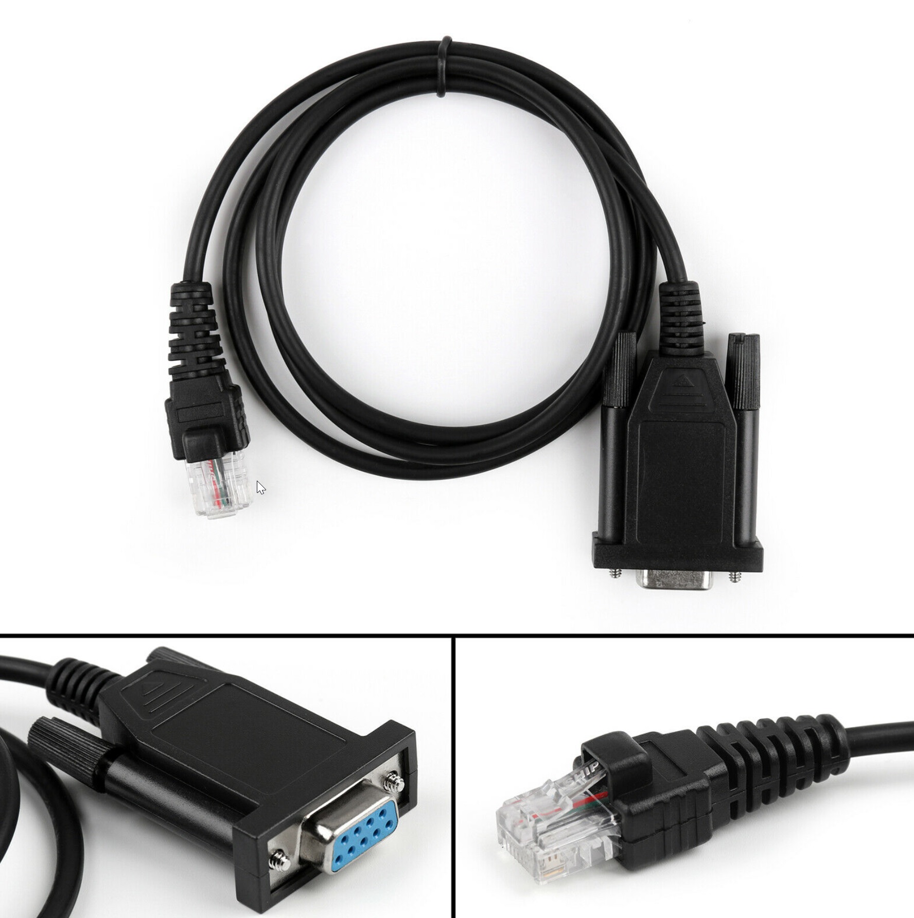
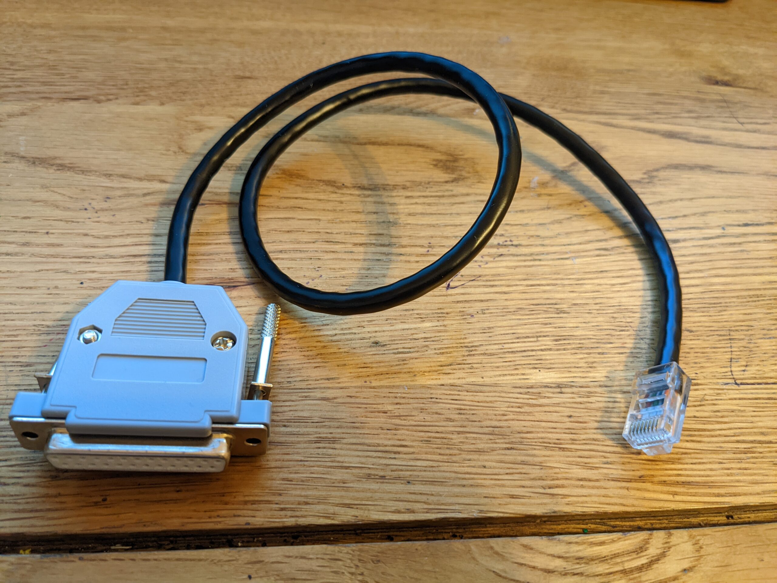
Before I decided to flash Motorola GM360 & GM340 radios, I used to program the radios in CPS software using ribless cables as shown on the pictures below. Ribless means you do not need any special box and the cable is connected straight to the computer. First ribless cable is the RS232 to port RJ45 (front microphone socket). It needs to be connected to the RS232 port in PC or to the special USB to RS232 cable:
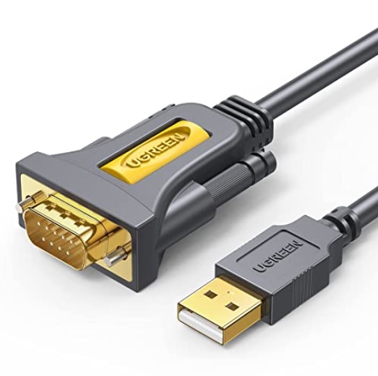
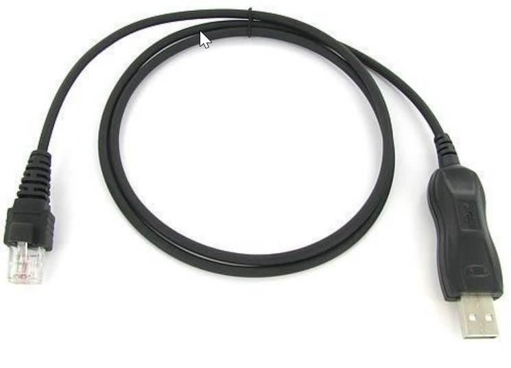
Second type of the ribless cable, is the USB to port RJ45 (front microphone socket). The cable needs to be connected straight to the USB, so you don’t even have to have any serial port in your PC!
Both cables above (plus third USB to RS232) are absolutely perfect for programming CPS (cpg) codeplugs to the radio.
But do not buy the cables above if you also want to flash the radio with the new firmware.
First of all the cables above are ribless. To flash the radio you need a RIB. You can buy a genuine Motorola RIB for roughly £150 or a aftermarket one for about £30:
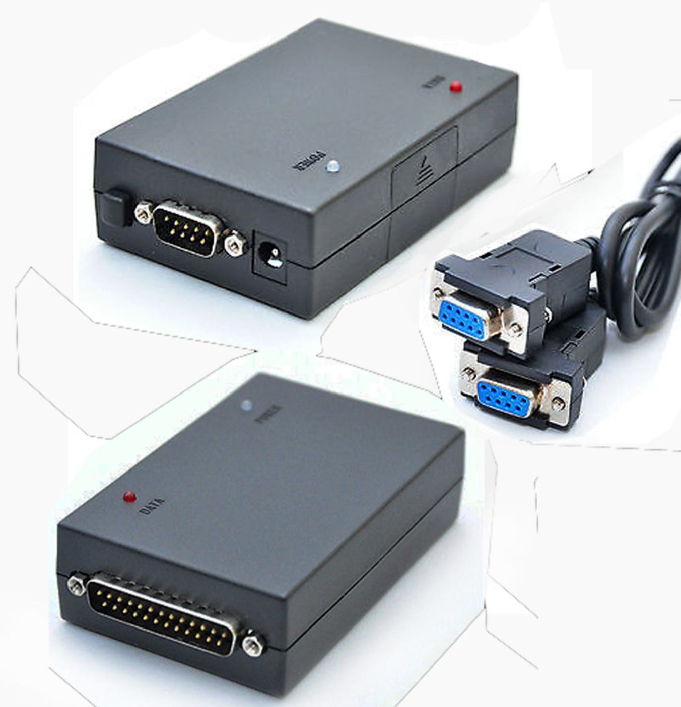
Now we also need a flashing box which you can buy, or it is extremely easy to make it yourself:
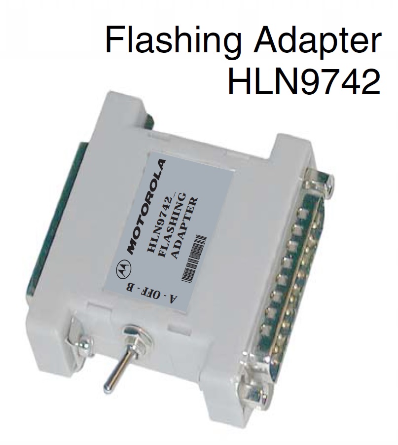
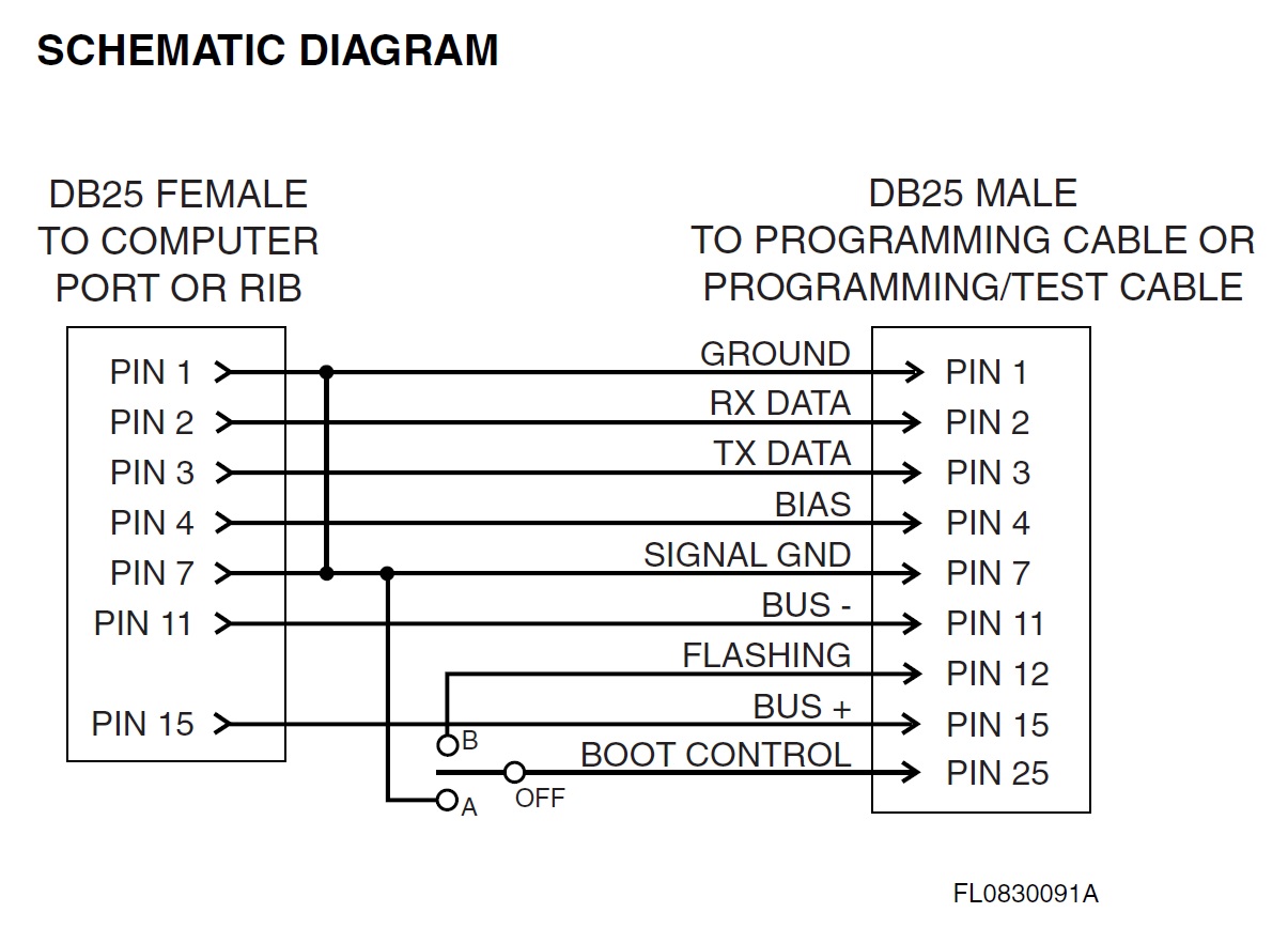
I found two diagrams showing the Motorola HLN9742 flashing box, the first one is a proper Motorola diagram, the second is the simplified box which I decided to make and it works perfectly, as for flashing you always need to use only A option (see further descriptions). Generally option B is used only for flashing through the front microphone socket.
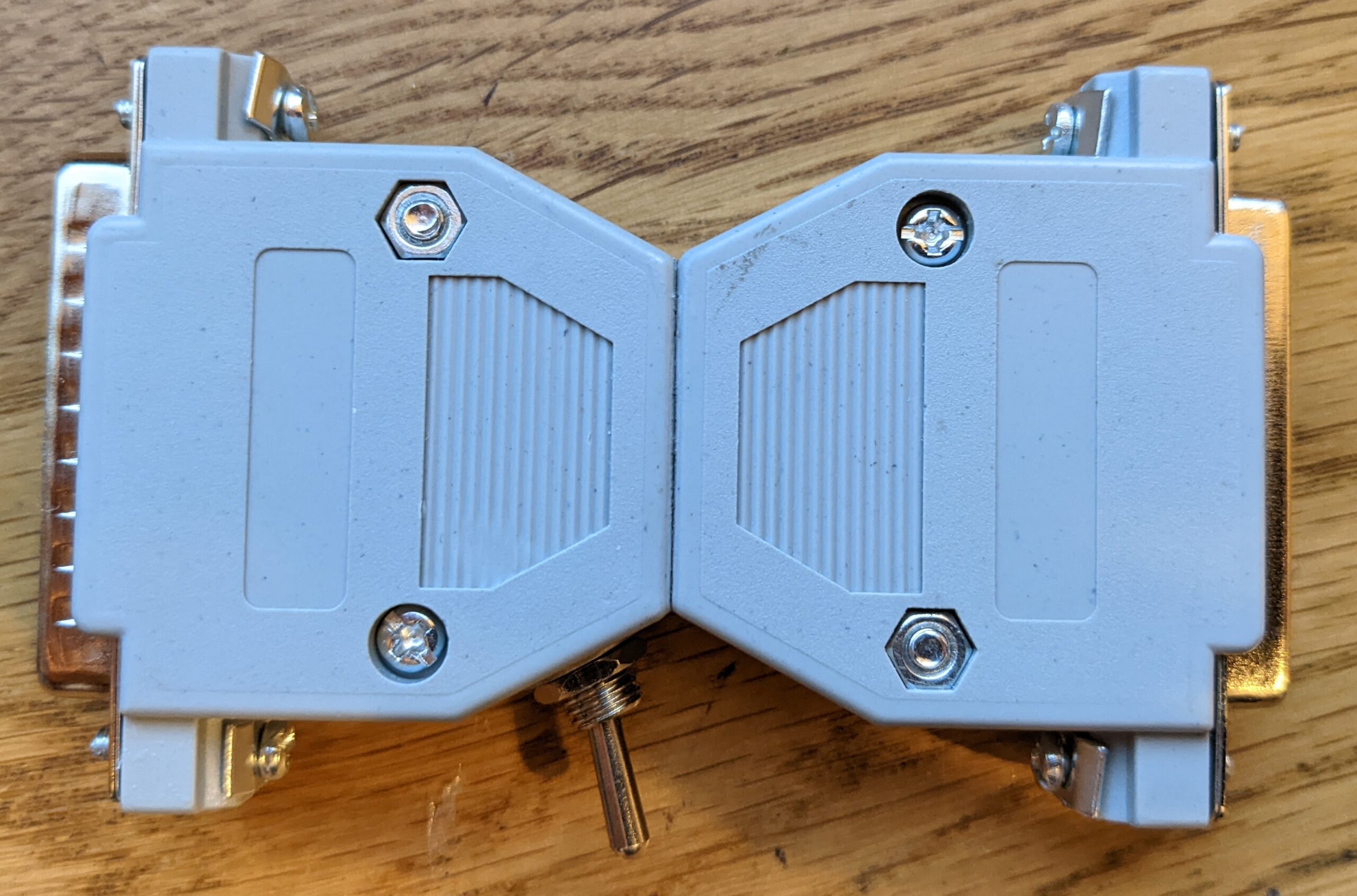
And this is how I made my own one:
So the Motorola RIB is connected to the computer, then you connect the flashing box above and then you need a cable from flashing box to the radio. So I decided to make a cable myself, as I easily found diagrams on internet:
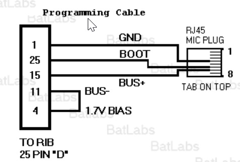
Now bad news: the cable worked with a RIB only for CPS (cpg) codeplug uploading. It did not want to work as a flashing cable 🙁 I am not sure if it is possible to flash the radio using the front microphone RJ45 socket. So finally I found the diagram of the cable which works correctly for both CPS programming and ***also*** for flashing the radio. However, the cable is going into the back accessories socket. Diagram for the cable is presented below. It is an official Motorola diagram for the testing and programming cable called Motorola RKN4083:
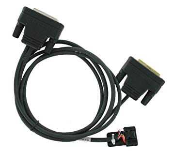
So you can buy one or you can make one yourself. However, the cable is also for a testing station so it is a bit complicated. There is absolutely not point to recreate it if you are not going to use a testing station. Please see the picture below showing modified diagram. It also shows the pinout for the back motorola socket, looking from the back of the radio:
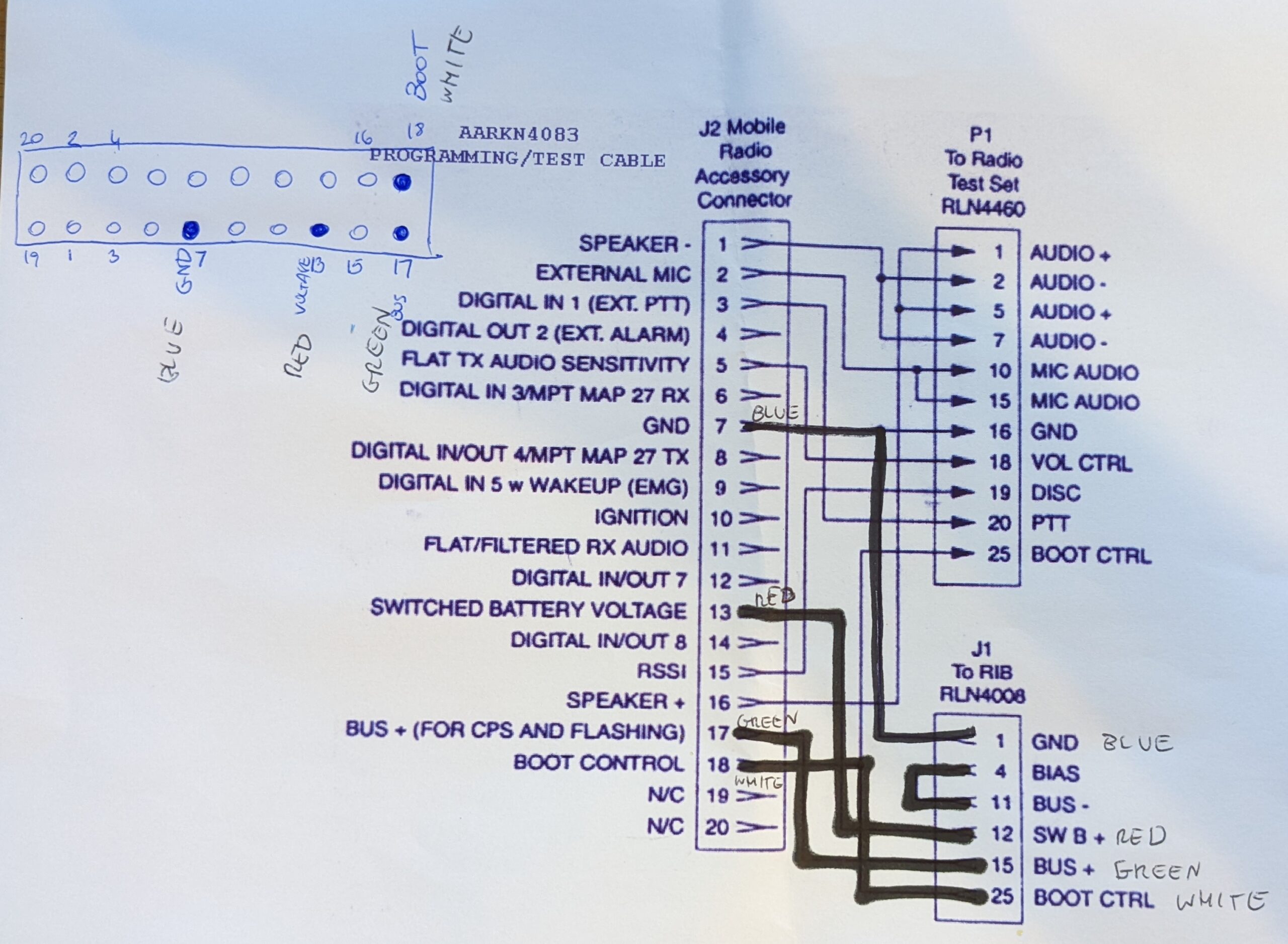
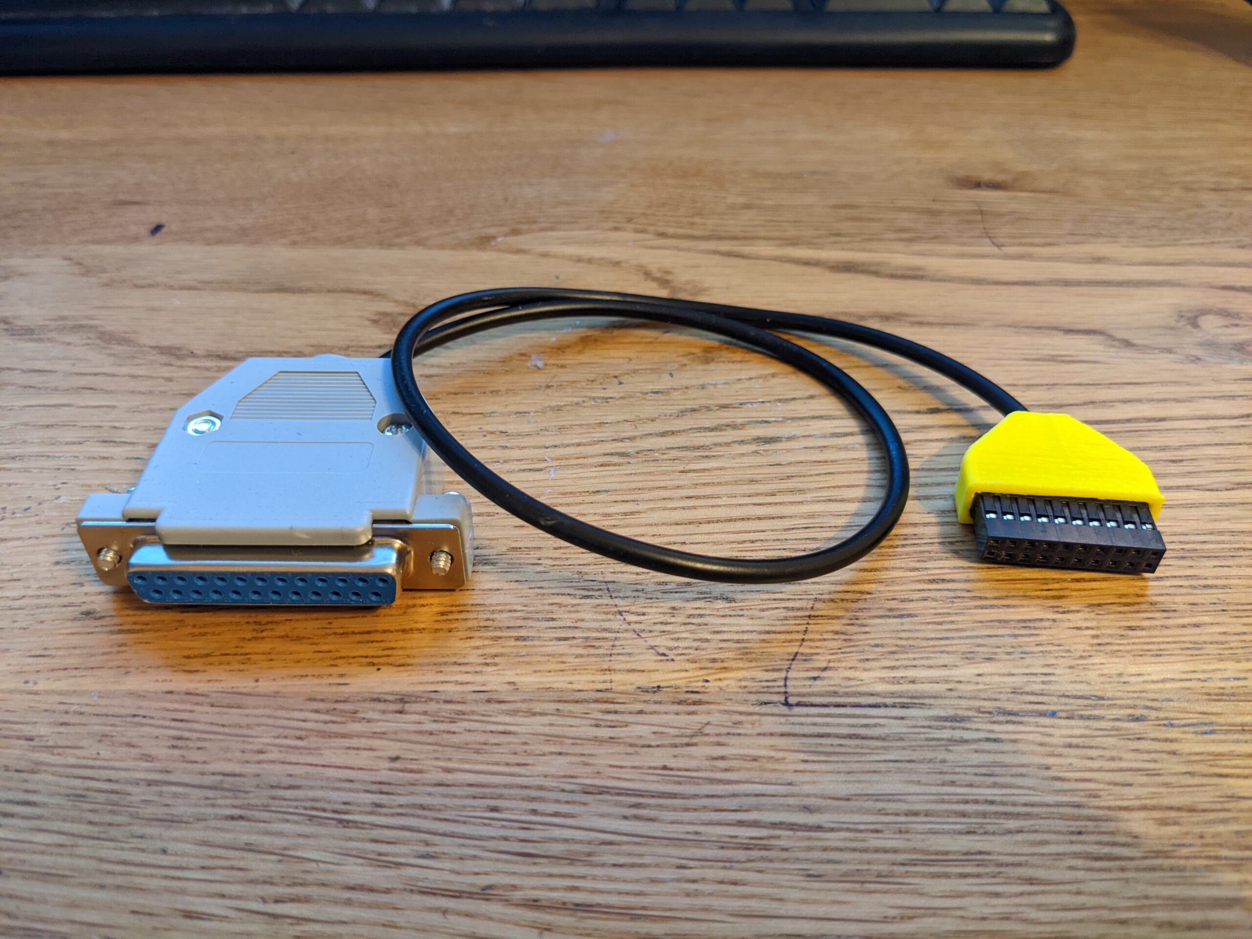
Basically you need to ignore any wires going to P1 plug. Also description saying “J1 to RIB” is confusing. When you are flashing the radio, the cable is going to the flashing box HLN9742! You can ignore handwritten colours – I left them on the diagram just for myself when I was soldering pins. In the top left corner you can see the motorola accessories socket viewed from the back of the radio. Picture below shows how the cable looks like:
To make the accessories cable I had to buy a DuPont plug(s) with separated pins and soldered them together with thin wires. You can find them on eBay searching for DuPont 2.54mm Connector Sets With FEMALE Crimps (Single and Double Row).
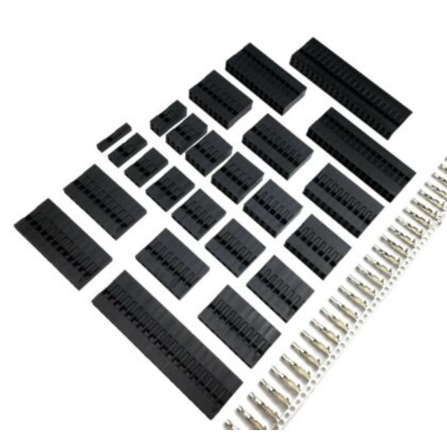
Also I decided to 3D print a casing for the plug, as once it is inside of the radio’s socket, it will be difficult to remove it without pliers, especially that for the mechanical stability I decided to populate ALL pins inside of the plug, even the unconnected ones. However, I think you can populate every second one. Using just 4 required pins will make the plug a bit “loose” feeling.
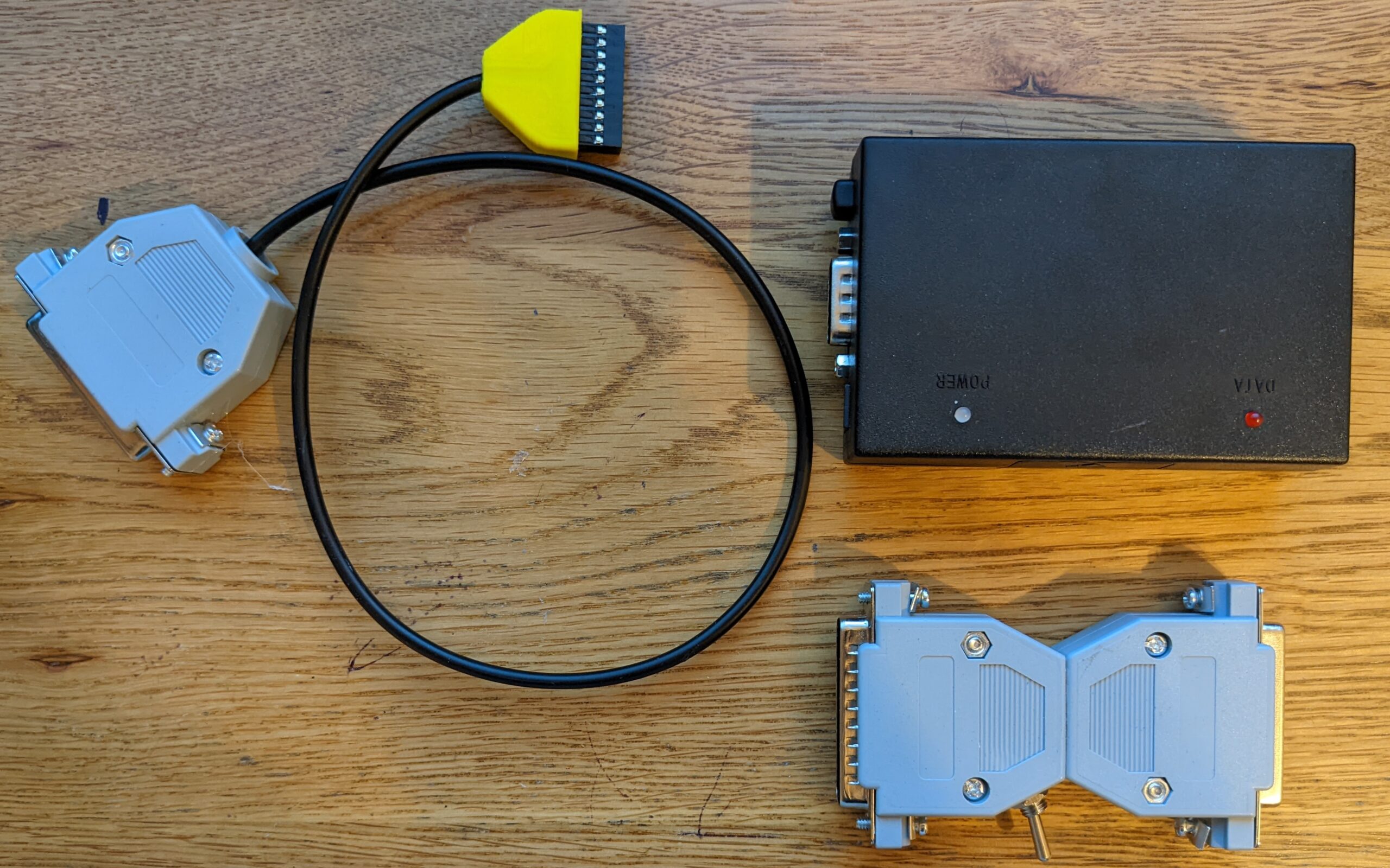
So the ready for you set looks like below:
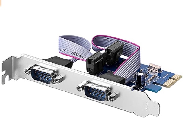
Also the important thing is that the computer should have a real RS232 port. If it does not have a proper RS232 port, buy a PCI-E card similar to the one below:
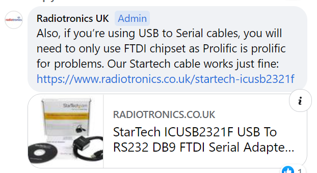
***Apparently*** instead of the RS232 card you can use a cable with microchip FTDI, for example StarTech ICUSB2321F – I have not tested this solution myself!
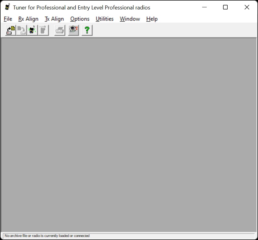
Important: ***BEFORE*** you flash the radio, please save your old version codeplug and ***also*** use software called “Tuner for Professional and Entry Level Professional Radios”. With the software read the radio and save all RF settings on your HDD. Flashing will erase them from the radio and will put all settings to default, so it is important to have the settings saved (*.sfp file). Edit: ***Apparently*** you do not have to save all RF settings in *,sfp file, as they are kept inside of CPS (cpg) files. I can’t confirm or refuse this. This is what I have recently heard.
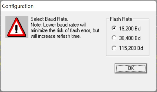
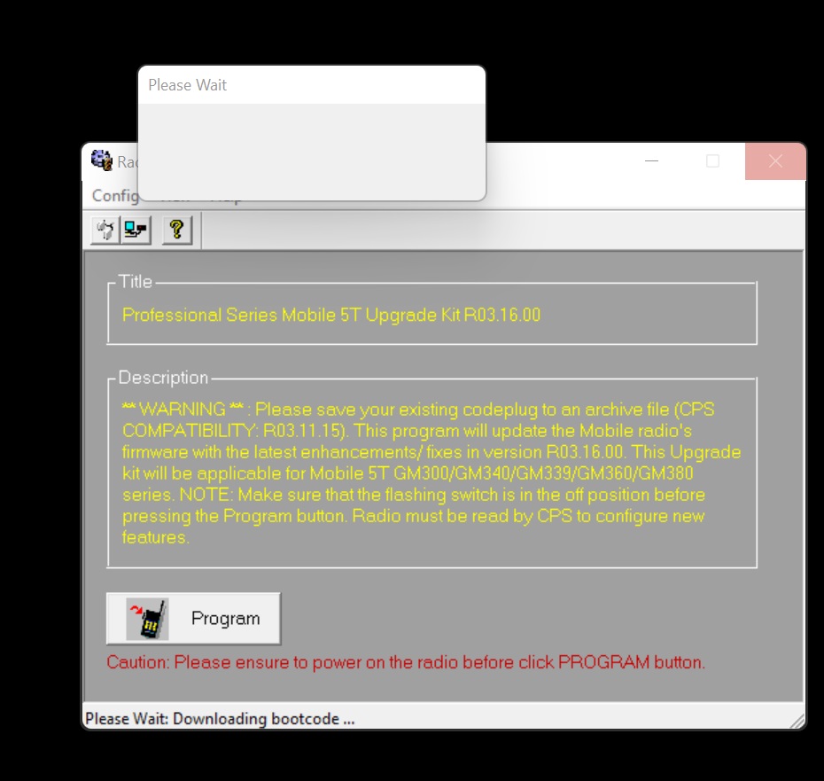
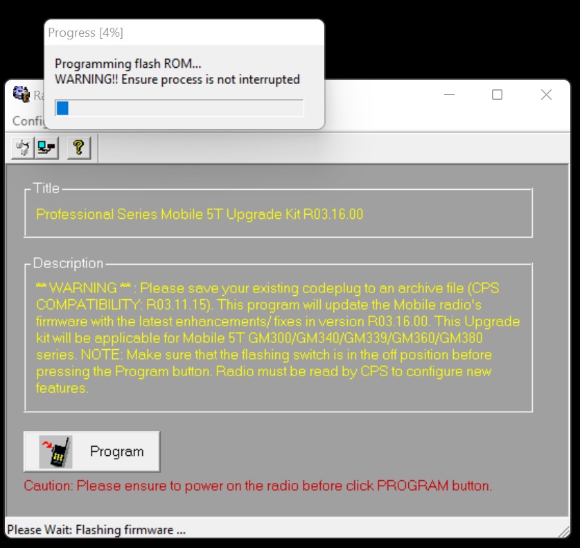
So now we can flash the radio. You need software called Radio Upgrade Kit, I downloaded it from https://www.radiotronics.co.uk/motorola-gm340-firmware-upgrade website.
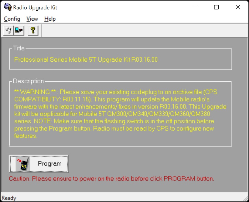
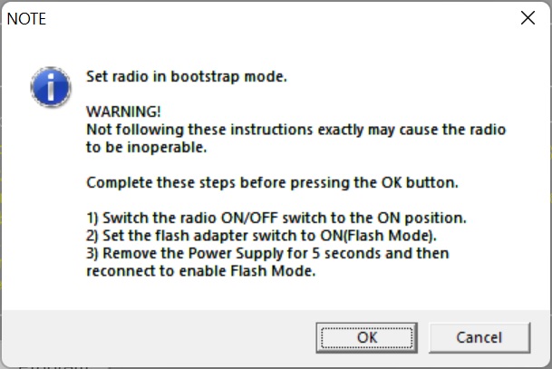
Unplug the power *cable* (I switch off the power supply) and wait 5 seconds, however because I found that it is easier for me just to turn off the power supply, sometimes because of the big capacitors in power supply I have to wait 1 minute to switch the power back!!! Then switch the power supply back on. Now another confusion – Motorola does not say anything about it at the picture above! You must switch the radio ON by pressing shortly the volume ON/OFF knob switch. Display will not start displaying anything. Now you can press the OK button on the window above.
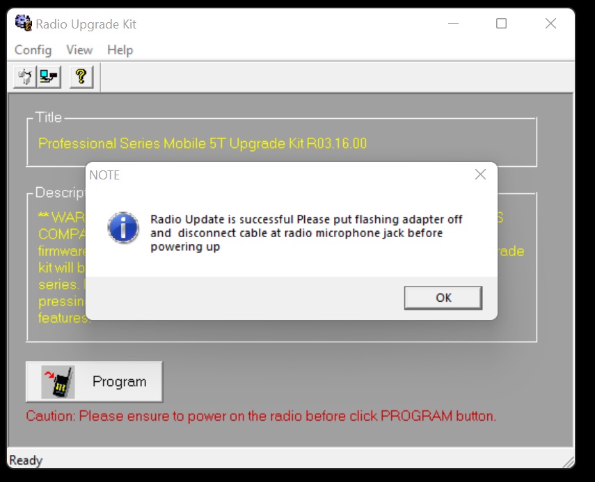
As shown above it is important to unplug the back accessories plug and (just to avoid risk in the future) move the switch in flashing box to off position. Instead of removing the plug, you can turn the RIB off (then it is really necessary to move the switch to off position), otherwise the radio will not start until you do it!
Just for your curiosity, you can, if you want, keep the flashing box HLN9742 connected all the time even for CPS programming however make sure the flashing switch is at “OFF” position!
Please do not forget that now you have to use “Tuner for Professional and Entry Level Professional Radios” software you need to upload back the radio RF settings (*.sfp file). Edit: as mentioned above, APPARENTLY *.sfp file is not required as all RF settings are also stored in the personalised for each radio CPS (cpg) file.
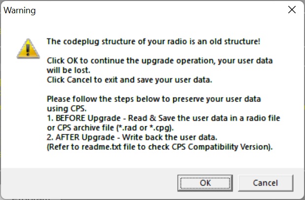
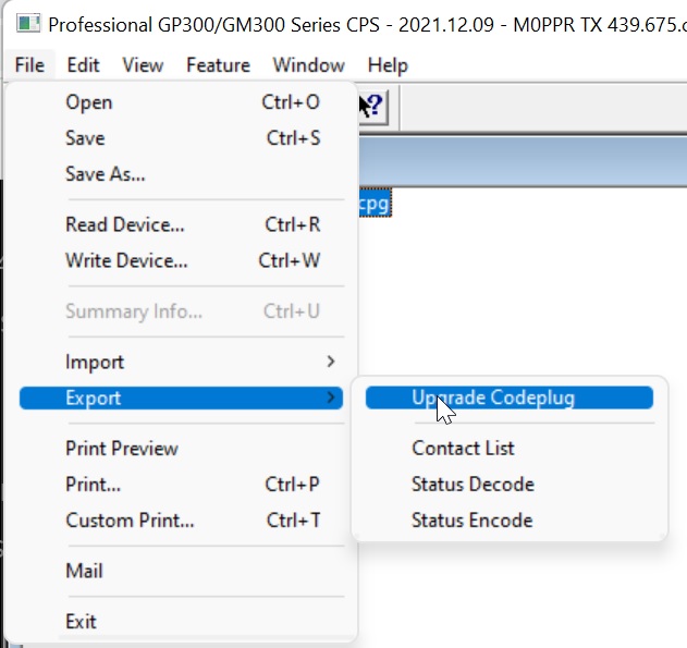
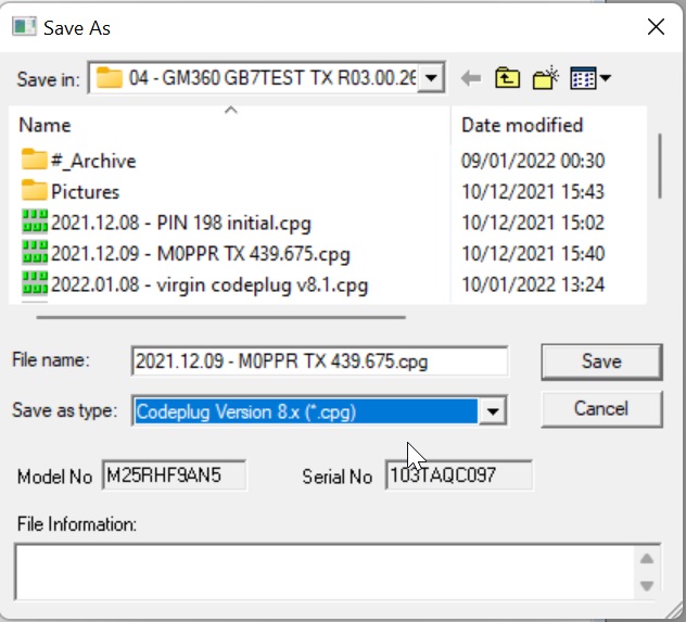
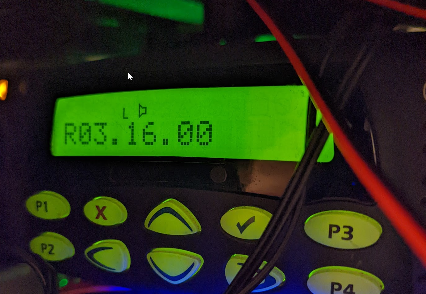
Now, if you try to upload the old version CPS file (cpg) for example in version 4 into the new v8.1 R03.16.00 firmware radio, the radio will refuse the file. Do not panic. Open CPS software and open the old codeplug cpg file and convert the old cpg file into the new version, as shown on the pictures below:
I hope the article was helpful.
In the cable from the 20 PIn radio connector to the adapter DB25 connecter, whey is there a wire (red) from pin13 to pin12? Pin12 is not connected in the flash adapter. I cannot seem to get my LabTool to recognise bootstrap mode.
Yes, you are absolutely correct! I did not realise that. Please do not forget those diagrams are not mine, they are done by Motorola. Maybe the wire is needed in different configuration. However, I followed the diagrams and it works for me.
Hi
Why didn’t you put the switch in the plug rather than the back to back plug/socket?
73 GB7JT repeater
I just tried to make it the same way as it’s done by Motorola
hi, i wanted to update gm399 radio “codeplug” but i am facing a problem. “test 4 failed” . I tried to update for r03.05.00 codeplug. Do you think I can fix this problem by myself?
Actually, do you try to update a firmware or do you try to update a new codeplug?
Hi, when do you get this error message?
“From the moment I first started using the walkie-talkie, I have been receiving this error message.”
“Due to a faulty update, the radio has lost its functionality; it can receive audio, but currently, it doesn’t transmit any sound. Additionally, there are codeplug version issues, and I have become completely puzzled about what to do . I actually just want the radio to start working now. I see that you have knowledge about the subject, please help me. Some information written on the radio is as follows: tanap:IMUE6038A ver.no:r03.05.00 model:m25rhn9an8 KIT:HLN8894A” TA2EM 73
“I managed to upgrade the Motorola GM 399 mobile radio to version r 03.16.00 successfully, but I have an issue. While I can receive signals from other radios, when I press the PTT button, it transmits with a frequency outside the range I set, and all that can be heard during the transmission is static noise. Do you have any thoughts on this problem? Codeplug version: 8.1, radio software version: r03.16.00.”
Hi, as I mentioned I am not professional Motorola guy, I just tried to help with the flashing procedure. There is a Motorola group on Facebook, maybe they will be able to help? In theory, it sounds like you do a simple mistake… How do you know you tx outside of the range? Do you talk about few kHz or it is miles away? If just few kHz , the radio may need tuning, to be done by other software .
Thanks for be interested. I think it was a very simple mistake, I didn’t make the radio ct settings, so the sound was coming, but it was not being sent from the radio.
I tried several applications to understand the error. one was the global tuner application. I messed around with the settings a bit randomly. Do you think this radio will cause problems in the long run?
Hi
And on a GP300? Is it the same procedure?
Cheers
Rob
I have no idea I am afraid…